249
16.24 Matsushita FP (Aromat)
16.24.1 HMI Setting
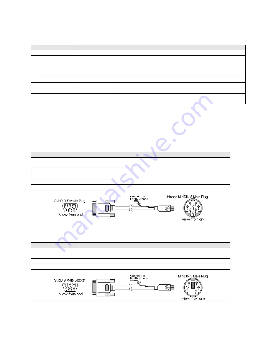
Communication parameters must be set the same as those of the PLC. The following settings are recommended.
Parameter
Recommended Setting Notes
Serial I/F port
RS232
Options: RS232, RS485 – Dependant on PLC hardware
Baud rate
9600
Options: 9600, 19200, 38400, 57600, 115200 - Must match PLC port
setting
Parity
Odd
Options: Odd, Even, None - Must match PLC port setting
Data bits
8
Options: 7, 8 - Must match PLC port setting
Stop bits
1
Options: 1, 2 - Must match PLC port setting
HMI station No.
0
Not used
PLC station No.
1
Must match PLC port setting (0-255)
Note:
FP3 must set 0
Comm. delay (10msec) 0
Request delay: 0~999 @10 milliseconds. Use when the PLC requires a
delay between requests. Not implemented in simulation mode.
16.24.2 PLC Setting
Communication parameters must be the same as those of the MMI.
Compatible with:
FP Sigma, FP0, FP1, FP2, FP2SH, FP10SH and FP3
16.24.3 Wiring
16.24.3.1
Wiring for cable connections using
Matsushita FP1 CPU’s
with Hirose MiniDIN RS422 ports.
KEP Part#: (Not Available) (D-Sub 9 Female Plug to Hirose MiniDIN 8 Male Cable)
HMI PLC[RS-485]
Connect to Matsushita FP1 CPU Port
1 RXD-
Æ
5 TXA-
2 RXD+
Æ
2 TXB+
3 TXD-
Æ
3 RXA-
4 TXD+
Æ
6 RXB+
5 GND
Æ
1 GND
Shield
Æ
Earth Ground
16.24.3.2
Wiring for cable connections using
Matsushita FP Sigma, FP0, FP2, FP2SH,
FPM CPU’s
with RS232 MiniDIN 5 ports.
KEP Part#: (Not Available) (D-Sub 9 Male Socket to MiniDIN 5 Male Cable)
HMI PLC[RS-232]
Connect to Matsushita FP Sigma, FP0, FP2, FP2SH or FPM CPU Port
2 RXD
Æ
5 TXD
3 TXD
Æ
3 RXD
5 GND
Æ
1 GND
Shield
Æ
Earth Ground
Summary of Contents for MMI-1500
Page 2: ...ii...


