253
16.25.2.2
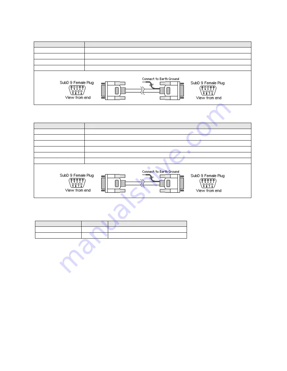
Wiring for HMI between
RS485 2W
D-Sub 9 Male Socket ports.
KEP Part#: (Not Available) (D-Sub 9 Female Plug to D-Sub 9 Female Plug Cable)
HMI PLC[RS-485]
Connect to HMI PLC[RS-485]
1 RXD-/TXA-
Æ
1 RXD-/TXA-
2 RXD+/TXB+
Æ
2 RXD+/TXB+
5 GND
Æ
5 GND
Shield
Æ
Earth Ground
16.25.2.3
Wiring for HMI between
RS485 4W
D-Sub 9 Male Socket ports.
KEP Part#: (Not Available) (D-Sub 9 Female Plug to D-Sub 9 Female Plug Cable)
HMI PLC[RS-485]
Connect to HMI PLC[RS-485]
1 RXD-
Æ
3 TXA-
2 RXD+
Æ
4 TXB+
3 TXD-
Æ
1 RXA-
4 TXD+
Æ
2 RXB+
5 GND
Æ
5 GND
Shield
Æ
Earth Ground
Note:
Graphic representation may not reflect the actual appearance of the finished cable.
16.25.3 HMI Memory Map Designations.
Device Name
Address
Range
MB (bits)
nnnh
nnn: 0 ~ 255 b: 0 ~ F(hex)
MW (words)
dddd
dddd: 0000 ~ 0511
Only 512 words are allocated for use. The first 255 words are also used as bit addresses. Word 0 contains bits 0000 through
000F, word 1 contains bits 0010 through 001F etc. Beware of using words that already have some of their bits designated for
use in the lower area. The same applies for long (double) words. Long words use up two words of memory and must be
designated with even numbered addresses.
Summary of Contents for MMI-1500
Page 2: ...ii...


