48
7.3.3.3 The Label Tab
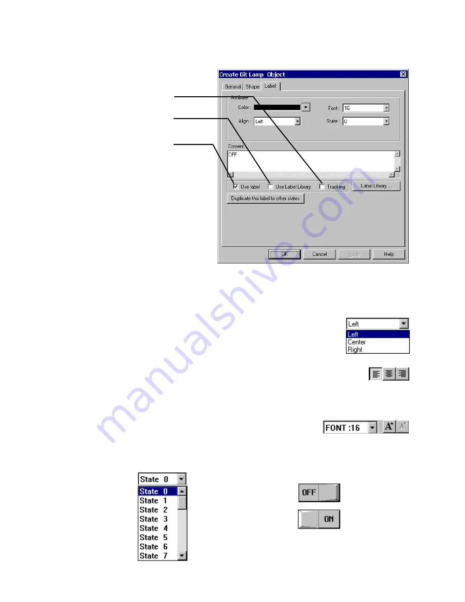
Labels are text that is shown on the face of the Switch, Lamp or other object (part). Different text can be assigned to different
states of a part. Example: State 0 = ”OFF”, State 1 = ”ON”.
Adding a Label to a Part
1. Click on
Label
tab
2. Select each state to label
3. Select Attributes for the label
4. Type the state’s label in the Content box
Color
Select a color for the text from the popup Color dialog. Colors can be changed from state to state. The Grayscale units have
a color selection of only 4 colors. If you have a color unit, there are 256 colors available. See the section on Drawing for
details about color selection.
Align
(Justification)
Select the desired text alignment. Alignment can vary from state to state. When the text input for a
Label becomes 2 lines or more, the alignment can be defined as
Left
,
Center
or
Right
justified.
Note:
Center
justifies the lines of text only; it does not center the text on the object.
Note:
Text alignment can be changed after a part is placed by using the text alignment tools in the tool bar.
Font
Select the desired font size. Font size can vary from state to state.
Font sizes 8, 16, 24, 32, 48, 64 and 96 are available.
Note:
Font size can be changed after a part is placed by using the font tools in the tool bar.
State
States are displayed only for those objects with multiple states. The text displayed for each state can be set independently.
Simply select a state in order to set its text, font, color and alignment.
Note:
The State can be viewed
after a part is placed by using
the State dropdown or State
Select buttons in the tool bar.
Select
Use
Label Library
to enable label
selection from a predefined set of Labels.
Select
Tracking
to place and move labels
of different states all at once and together.
Select
Use
Label
to enable label display.
State 0
State 1
Summary of Contents for MMI-1500
Page 2: ...ii...


