


14
RS232 / RS422 WIRING
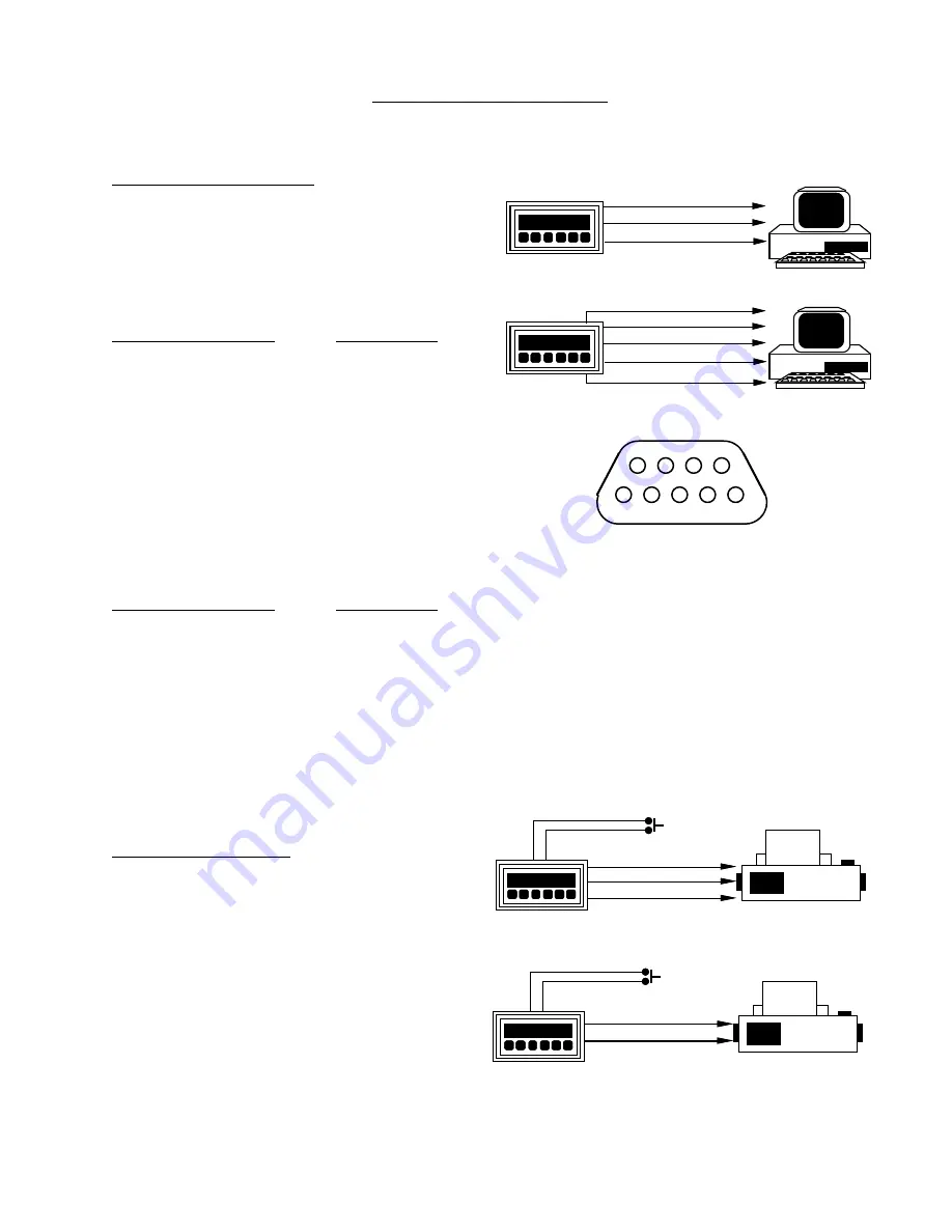
COMPUTER HOOKUP:
RS 232: When connecting the unit to a computer
with RS 232 communication, only three connec-
tions are needed. These connections are: Receive
data, Transmit data and Ground. The connections
should be made as follows:
DP -9 CONNECTOR
COMPUTER
Transmit data (pin 2)
Receive data
Receive data (pin 3)
Transmit data
Ground (pin 5)
Ground
RS 422: When connecting the unit to a computer
with RS 422, five connections are needed. These
connections are: Receive data A (+), Receive data
B (-), Transmit data A (+), Transmit data B (-) and
Ground. The connections should be made as fol-
lows:
DP -9 CONNECTOR
COMPUTER
Transmit data A(+) (pin 2) Receive data A(+)
Transmit data B(-) (pin 7) Receive data B(-)
Receive data A(+) (pin 3) Transmit data A(+)
Receive data B(-) (pin 8) Transmit data B(-)
Ground (pin 5)
Ground
PRINTER HOOKUP:
When connecting the unit to a printer, you must
first program the desired baud rate, parity and
strobe list with a computer. After the unit is
programmed it can be connected to the printer.
Connect the transmit line(s) of the unit to the
receive line(s) of the printer and be sure that both
devices have common grounds. When the strobe
line is triggered the unit will transmit the selected
strobe list which you had previously programmed.
TRANSMIT PIN (2)
GROUND PIN (5)
RECEIVE PIN (3)
TRANSMIT A(+)PIN (2)
TRANSMIT B(-) PIN (7)
RECEIVE B(-)PIN (8)
RECEIVE A(+)PIN (3)
GROUND PIN (5)
RS 232
RS 422
1
2
3
4
5
6
7
8
9
RS 232
1. INITIALIZE
2. TRANSMIT
3. RECEIVE
4. N/C
5. GROUND
6. STROBE
7. N/C
8. N/C
9. N/C
RS 422
1. INITIALIZE
2. TRANSMIT A (+)
3. RECEIVE A (+)
4. N/C
5. GROUND
6. STROBE
7. TRANSMIT B (+)
8. RECEIVE B (+)
9. N/C
TRANSMIT A (+) PIN (2)
GROUND PIN (5)
+12V PIN 7
(bottom board)
STROBE PIN (6)
TRANSMIT B (-)PIN (7)
RS 232
RS 422
TRANSMIT PIN (2)
GROUND PIN (5)
+12V PIN 7
(bottom board)
STROBE PIN (6)


