


2
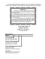
MOUNTING
HOW TO MOUNT:
Slide the body of the unit through the rubber gasket. Insert the unit into the panel. Slide the
brackets up the groove to press against the back of the panel, as shown in "FIG. A". Insert
the screws into the rear of the brackets.
Tighten the screws evenly and alternately. A panel less than .1" may distort if the clamps are
screwed too tightly. Do not over tighten! A normal level of torque is required. Maximum torque
should be 3" pounds.
FIG. A
3.622
(92)
3.925
(99.7)
4.437
(112.7)
2.625
(66.68
4.245
(107.8)
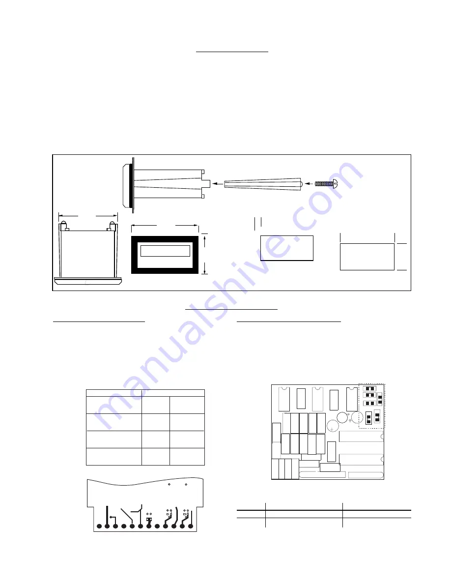
JUMPER OPTIONS
Output Jumper Selections
Before making any board modifications, be sure power is
disconnected and locate the plastic extender to the case at
the rear of the unit. To remove the extender locate and
remove the two screws which hold it in place. After the
extender is removed the PC board will be exposed.
The unit must be removed from the case to access jumpers
C & F, all other jumbers can be accessed by removing the
plastic extender.
J4
J5
J6
J3
J1
J2
CR1
R3
C8
R7
R5
R4
U1
CR2
REV
20229
CR6
CR3
U3
P1
R10
R6
C6
C7
CR4
CR5
C4
R2
R1
C3
C5
U2
U4
U6
U5
R8
R9
C1
C2
C9
B
C=CLOSE, O=OPEN
4-30V INPUT
Millivolt INPUT
Input A
J1-O, J2-C, J3-O
J1-C, J2-O, J3-C
InputB
J4-O, J5-C, J6-O
J4-C, J5-O, J6-C
Mag. Input Jumper Selections
If the unit has the millivolt input bd.# 20229, A & B inputs
can be separately solder jumper programmed to accept
either a low millivolt or 4-30 V input. Each unit shipped is
programmed according to part number. If solder jumpers
are made, the part number should be modified to reflect the
changes made
FUNCTION
"A" RELAY
N.C. OUTPUT
"B" RELAY
N.C. OUTPUT
"A" PRESET
TRANSISTOR (NPN)
"B" PRESET
TRANSISTOR (NPN)
MODIFICATION
CUT JUMPER
AT "A" "B" TO "2"
CUT JUMPER
AT "D" "E" TO "4"
CUT JUMPER
AT "A" "C" TO "2"
CUT JUMPER
AT "D" "F" TO "4"
BOTTOM VIEW AT TERMINAL
D
E
G
H
20192
12 11 10 9 8 7 6 5 4 3 2 1
L
4
A
B
2
F
C


