background image

Summary of Contents for ATE 100-0.5

Page 1: ...equesting the correct revision for your par ticular model and serial number 3 The contents of this manual are protected by copyright Reproduction of any part can be made only with the specific written permission of Kepco Inc Data subject to change without notice KEPCO THE POWER SUPPLIER KEPCO INC 131 38 SANFORD AVENUE FLUSHING NY 11355 U S A TEL 718 461 7000 FAX 718 767 1102 email hq kepcopower co...

Page 2: ......

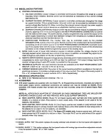
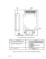
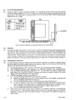
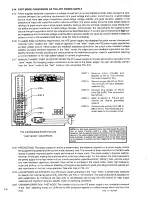
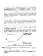
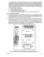
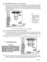
Page 3: ...sing remote sensing For local sensing leave the links between TB201 terminals 2 S and 3 M and between terminals 5 M and 6 S in place Discon nect the remote sensing wires from TB 201 terminals 2 S and 6 S to the load C PAR 3 37 through 3 90 REDUCING RISE TIME DELAY WHEN USING EXTERNAL PROGRAMMING EITHER FAST OR SLOW MODE To reduce the rise time delay make sure that for the low level of the programm...

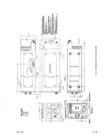
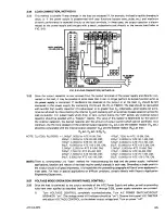
Page 4: ...PC 12 5 To reduce a c line related noise at the output connect one of the following to the ATE chassis GND terminal 1 the return of the programmind source 2 the corresponding output terminal of the ATE or 3 the corresponding Load terminal In addition make sure that all devices are tied to the same GND con nection it is recommended that all devices in use by powered by the same a c outlet E FIGURE ...

Page 5: ... EFT ESD Level 4 Surge Immunity Criteria B Flicker designed to meet Radiated Immunity designed to meet Conducted Immunity Magnetic Field Immunity designed to meet Manufacturer s Name Manufacturer s Address KEPCO INC 131 38 SANFORD AVENUE FLUSHING NY 11355 USA Importer s Name Importer s Address Type of Equipment Component Power Supply Model Series ATE 50W 100W Rack 250W Rack 500W Rack 1000W Full Ra...

Page 6: ...lled within a suitably wired equipment rack utilizing a three wire grounded mains con nection See wiring section of this manual for complete electrical wiring instructions EN61010 1 Cl 6 5 4 and Cl 6 10 1 5 This power supply has secondary output circuits that are considered hazardous and which exceed 240 VA at a potential of 2V or more 6 The output wiring terminals of this power supply has not bee...

Page 7: ...r connection on the product s rear panel To reconfigure the product input for other nominal mains voltages as listed herein the product must be modified by a trained service technician The PROTECTIVE EARTHING CONDUCTOR TERMINAL must be properly con nected prior to application of source power to the product see instructions on instal lation herein in order to ensure safety from electric shock PROTE...

Page 8: ......

Page 9: ......

Page 10: ......

Page 11: ......

Page 12: ......

Page 13: ......

Page 14: ......

Page 15: ......

Page 16: ......

Page 17: ......

Page 18: ......

Page 19: ......

Page 20: ......

Page 21: ......

Page 22: ......

Page 23: ......

Page 24: ......

Page 25: ......

Page 26: ......

Page 27: ......

Page 28: ......

Page 29: ......

Page 30: ......

Page 31: ......

Page 32: ......

Page 33: ......

Page 34: ......

Page 35: ......

Page 36: ......

Page 37: ......

Page 38: ......

Page 39: ......

Page 40: ......

Page 41: ......

Page 42: ......

Page 43: ......

Page 44: ......

Page 45: ......

Page 46: ......

Page 47: ......

Page 48: ......

Page 49: ......

Page 50: ......

Page 51: ......

Page 52: ......

Page 53: ......

Page 54: ......

Page 55: ......

Page 56: ......

Page 57: ......

Page 58: ......

Page 59: ......

Page 60: ......

Reviews: