4-6
BHK-MG (OPR) 032816
ure 4-2. If an
Initialization Error
message appears, either the IVI Shared components or
VISA-COM was not installed correctly. Return to step 1 and reinstall the driver.
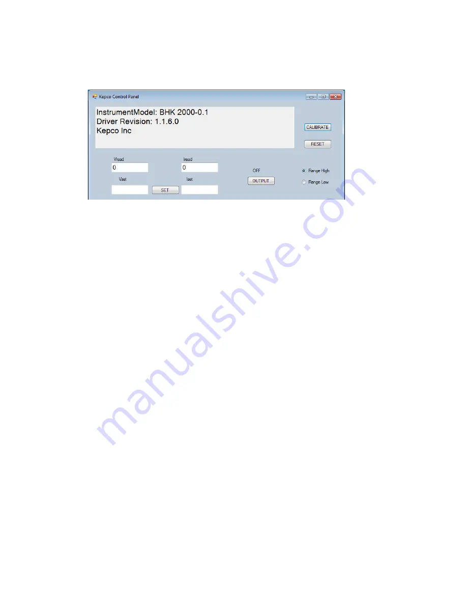
FIGURE 4-2. MAIN CONTROL PANEL, TYPICAL
4.4.2
MAIN CONTROL PANEL
The main control panel allows setting the voltage and current, enabling and disabling the output,
selecting the current range (full rack units), resetting the unit, and calibrating the unit.
1. To set the unit's voltage and current, enter the values into the
Vset
and
Iset
boxes, respec-
tively, and click the
SET
button.
2. To enable or disable the output, click the
OUTPUT
button.
3. To reset the unit to power-up state (output OFF, voltage and current set to 0), click the
RESET
button.
4. Range High and Range Low radio buttons allow range selection (full rack units only).
4.4.3
CALIBRATION CONTROLS
NOTE
:
Before performing calibration, set BHK for local sensing (cS to + OUT
terminal and connect –S to –OUT terminal at the rear panel).
After turning the
unit on it is necessary to wait 15 minutes before calibrating the unit to allow
for thermal stabilization.
NOTE: The left and right single arrow buttons (
<
and
>
) that appear on the calibration screens
are equivalent to the front panel left and right arrow keys. The left double arrow button
(
<<
) is equivalent to the
1
key on the front panel keypad; the right double arrow button
(
>>
) is equivalent to the
3
key.
All adjustments are done using the four arrow buttons that appear during Calibration (see Figure
4-3 and Table 4-2). The double arrow buttons
<<
and
>>
either increase (
>>
) or decrease (
<<
)
Summary of Contents for BHK 1000-0.2MG
Page 2: ......
Page 6: ......
Page 17: ...BHK MG032816 xi FIGURE 1 1 BHK MG SERIES PROGRAMMABLE POWER SUPPLY ...
Page 18: ...xii BHK MG032816 ...
Page 46: ......
Page 101: ...BHK MG OPR 032816 3 55 FIGURE 3 20 SERIES AUTOMATIC CONFIGURATION ...
Page 109: ...BHK MG OPR 032816 3 63 FIGURE 3 23 PARALLEL AUTOMATIC CONFIGURATION ...
Page 114: ...3 68 BHK MG OPR 032816 FIGURE 3 25 PARALLEL MASTER SLAVE CURRENT MODE CONFIGURATION ...
Page 116: ......
Page 154: ......


