background image

 102607

228-1616 REV 2

3

KEPCO, INC. 

 " 

 131-38 SANFORD AVENUE 

 "

  FLUSHING, NY. 11355 U.S.A.

  "

  TEL (718) 461-7000

  " 

 FAX (718) 767-1102


http://www.kepcopower.com   

 email: hq@kepcopower.com

ACCESSORIES. 

See Table 3.

SAFETY. 

See Table 

4

TABLE 3.  ACCESSORIES

ITEM

FUNCTION

KEPCO

PART NUMBER

Line Cord Set (125V/20A)

2.5m long cord set, provides for source power 
connection. Mates with NEMA 5-20R receptacle 
(see adjacent figure). Supports rated load power 
over mains voltage range of 90-136V a-c.

NEMA 5-20R

118-0776

Line Cord Set (125V/15A)

2.5m long cord set, provides for source power 
connection. Mates with NEMA 5-15R receptacle 
(see adjacent figure). Supports restricted load 
power over mains voltage range of 90-136V a-c 
(contact Kepco Sales Engineering for details).

NEMA 5-15R

118-1136

Line Cord Set (250V/15A)

2.5m long cord set, provides for source power 
connection. Mates with NEMA 6-15R receptacle 
(see adjacent figure). Supports rated load power 
over mains voltage range of 180-265V a-c.

NEMA 6-15R

118-1137

IEEE 488 (GPIB) Cable, 1m long

Connect KLP Power Supply to GPIB bus.

SNC 488-1

IEEE 488 (GPIB) Cable, 2m long

Connect KLP Power Supply to GPIB bus.

SNC 488-2

IEEE 488 (GPIB) Cable, 4m long

Connect KLP Power Supply to GPIB bus.

SNC 488-4

Chassis Slide

Allows rack-mounted units to slide in and out. Two (2) slides required 
per power supply.

108-0239 

(Jonathan 

375-QD Series)

Analog Connector Backshell

Locks analog port mating connector to KLP via jackscrews.

108-0204

Loop Back Test Connector

Used for verification of RS 232 operation.

195-0112

Null Modem Cable 

Connect RS 232 port with controlling computer, DB9F to DB9F, 10 ft 
long

118-1176

LAN Patch cable

Connects KLP LAN port to LAN, 10 ft long.

118-1115

Support bracket, rear

Provides extra support to rear of rack-mounted unit if needed. Two 
brackets required per unit. Each bracket requires 2 screws and 2 
washers. See Figure 4, sheet 1, Detail “A” for requirements. 

128-2306

TABLE 4.  SAFETY SYMBOLS

SYMBOL

MEANING

CAUTION: RISK OF ELECTRIC SHOCK.

CAUTION: REFER TO REFERENCED PROCEDURE.

WARNING

INDICATES THE POSSIBILITY OF BODILY INJURY OR DEATH.

CAUTION

INDICATES THE POSSIBILITY OF EQUIPMENT DAMAGE.

!

Summary of Contents for KLP 10-150-3

Page 1: ...ch can be printed as a handy reference Refer to the KLP Developer s Guide for a full description of the digital interfaces their associated drivers and the SCPI command language The User Manual Developer s Guide and drivers are found on the enclosed CD or can be downloaded from the Kepco web site at www kepcopower com support CONTENTS DESCRIPTION 2 UNPACKING 2 EQUIPMENT SUPPLIED 2 ACCESSORIES 3 SA...

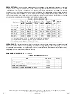
Page 2: ... If any indication of damage is found file an imme diate claim with the responsible transport service EQUIPMENT SUPPLIED See Table 2 TABLE 1 MODEL PARAMETERS Model number Rated Voltage Range 1 Maximum current for rated voltage Minimum programmable current Rated Current Range 1 Maximum voltage for rated current Ripple and noise p p 2 Efficiency 115 Va c KLP 10 150 3 0 10V 120A 10V 3 2A 0 150A 8V 15...

Page 3: ... NEMA 6 15R 118 1137 IEEE 488 GPIB Cable 1m long Connect KLP Power Supply to GPIB bus SNC 488 1 IEEE 488 GPIB Cable 2m long Connect KLP Power Supply to GPIB bus SNC 488 2 IEEE 488 GPIB Cable 4m long Connect KLP Power Supply to GPIB bus SNC 488 4 Chassis Slide Allows rack mounted units to slide in and out Two 2 slides required per power supply 108 0239 Jonathan 375 QD Series Analog Connector Backsh...

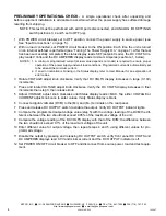
Page 4: ...an error indication is blinking in the Status display refer to User Manual for an explanation of error codes 3 Rotate VOLTAGE adjust knob clockwise Verify that DC VOLTS display increases in large X 100 increments 4 Press and rotate VOLTAGE adjust knob clockwise Verify the DC VOLTS display increases in finer increments than step 3 then release knob 5 Adjust VOLTAGE adjust knob clockwise until Statu...

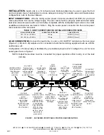
Page 5: ...ANEL CONTROLS AND INDICATORS TABLE 5 INPUT CURRENT SERVICE RATING AND CONDUCTOR SIZES MAINS VOLTAGE RANGE CURRENT SERVICE RATING CONDUCTOR SIZE 100 132V a c 50 60Hz 20 Amp 12AWG 2 0 mm 180 265V a c 50 60Hz 15 Amp 14AWG 3 0 mm POWER ON OFF Turns unit on off Circuit Breaker gives input protection VOLTAGE control momentary switch Rotate to set output voltage Tap to enter SETPOINT mode Also used for o...

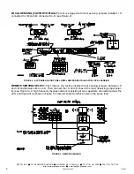
Page 6: ... S see Figure 2 FIGURE 2 KLP SERIES REAR PANEL VIEW JUMPERS INSTALLED FOR LOCAL SENSING REMOTE SENSING SELECT First remove the factory installed local sensing jumpers between S and M and between M and S Then connect the S and S lines at the load observing proper polar ity see Figure 3 A high frequency bypass network consisting of two capacitors connected across the error sensing point as shown in ...

Page 7: ...anual are Quick Boot eliminating the power up displays use of the internal relay and operation via the LAN interface or analog signals An Installa tion Operation Summary is also included in the User manual The Developer s Guide covers the GPIB and RS 232 and LAN interfaces including the use of the drivers supplied on the CD TURNING THE POWER SUPPLY ON To turn the power supply on set POWER ON OFF c...

Page 8: ... DC AMPERES displays show the actual output voltage and current Before enabling the output ALWAYS check the set points to avoid possible damage to the load 1 Tap either the VOLTAGE or CURRENT control The status display reads SET and the DC VOLTS and DC AMPERES displays show the stored setpoints 2 To accept the displayed value tap the associated adjustment control again To change the value rotate t...

Page 9: ...play does not change since it is showing actual output current Similarly rotating the VOLTAGE control while in CC mode affects the voltage limit To change the limits to a precise value refer to SETPOINT ADJUSTMENT Voltage and current settings are not allowed to exceed either a the virtual model setting or b 80 of the protection value Attempts to set voltage or current beyond these limits will not ...

Page 10: ...tches the output off flashes an overvoltage OVP or overcurrent OCP protection error message on the status display and sets a status bit that can be retrieved through the RS 232 GPIB or LAN port The unit must be cycled on and off to restore the output The maximum values are 1 2 x EOmax for overvoltage protection and 1 2 x IOmax for overcurrent protection A built in feature prevents the unit from be...

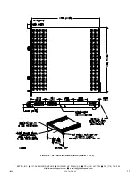
Page 11: ...607 228 1616 REV 2 11 KEPCO INC 131 38 SANFORD AVENUE FLUSHING NY 11355 U S A TEL 718 461 7000 FAX 718 767 1102 http www kepcopower com email hq kepcopower com FIGURE 4 KLP OUTLINE DIMENSIONS SHEET 1 OF 2 ...

Page 12: ...228 1616 REV 2 102607 KEPCO INC 131 38 SANFORD AVENUE FLUSHING NY 11355 U S A TEL 718 461 7000 FAX 718 767 1102 http www kepcopower com email hq kepcopower com FIGURE 4 KLP OUTLINE DIMENSIONS SHEET 2 OF 2 ...

Page 13: ......

Page 14: ......

Page 15: ...he Company parts or materials for which replacement is requested shall be returned to the Company for examination with shipping charges prepaid by the Purchaser Final determination as to whether a product is actually defective rests with the Company This warranty does not extend to any product which has been subjected to misuse neglect accident improper installation or use in violation of instruct...

Page 16: ...FOLD HERE Please place stamp here KEPCO INC 131 38 SANFORD AVE FLUSHING NY 11355 USA CUT HERE ...

Reviews: