SELENA
Multifunctional LED Clock
USER MANUAL V32D
KERA TECHNOLOGIES INC. 2013
www.ledclocks.com
19
right corner of the display will be flashing to indicate that the timer is running in the background. To see the timer then, press
the STRT key ( or SET or STOP key ) on the remote.
2) If using the external Start/Stop/Reset inputs for the timer:
After finished using the timer, press the "SCAN" key on the remote or activate the external RESET input and hold it for
5
seconds.
In both cases the display will go back to the real time clock display mode.
OTHER possible MODES:
Depending upon the desired operation, the clock may be set to alternate between the timer and the real time clock display,
even if the timer is not presently running.
To do that, enable the function Fn 7 and have the function Fn 3 also enabled ( default ).
Generally, the first 8 functions ( Fn 0 to Fn 7 ) control what the display will show in the alternating mode. The timer display
screen is Fn 7.
However, the timer display can be initiated at any time even if Fn 7 is not enabled, as described above, by pressing any of the
timer keys on the remote or activating any of the timer external inputs ( Start/Stop/Reset ).
If the display is set to alternate, pressing the HOLD key at any time, will stop the alternating mode.
To resume the alternating press the SCAN key.
This way, even if several screens are alternating, like: time, timer, date, temperatures ( if installed ), Julian day ( if installed ), it
is possible to FREEZE the particular screen by pressing the HOLD key while the desired screen is on the display.
EXTERNAL START / STOP / RESET INPUTS
FOR UP / DOWN TIMER / STOPWATCH and EVENT COUNTER
( Optional Feature )
The SELENA timers and event counters may be set up to use external inputs for Start, Stop (count UP, count DOWN) and
Reset. These inputs are available via the screw terminal block accessible at the back panel ( if installed ).
To activate the External Inputs for the Up/Down Timer/Stopwatch or Event Counter, enable the function Fn 36.
CAUTION:
External inputs may be connected to
DRY CONTACTS ONLY.
Any voltage carrying signals connected to those
inputs may
cause irreversible damage
. However, in special applications it is possible to apply a voltage within the range from
0 to +5V between the Common (0V) and any of the external control inputs if an external current limiting resistor is also used.
NOTE
: If the function
Fn 59
is also enabled, the timer may be operated via the remote concurrently with the external inputs.
The Timer activated via the external inputs behaves in a similar fashion as when it is operated using the Remote Control unit.
However, note the following:
1.
The Timer or Counter initial count may be preset only via the remote control (by pressing the SET key).
2.
A) If the Function
Fn 58
is
NOT ENABLED
, activating the START input will start the timer only if it was previously
RESET either by activating the external RESET input, or via the remote control, by pressing the SET or CLR key.
In the Event Counter mode (Fn 31), the count will be incremented by 1.
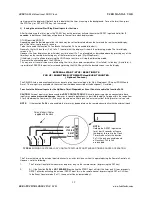
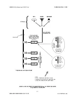
Common
RESET
STOP / DN
START / UP
TYPICAL
WIRING OF EXTERNAL DRY CONTACT SWITCHES FOR STANDARD TIMER/COUNTER OPERATION
BLACK
Colors of wires if Cables
supplied with the clock
RED
WHITE
GREEN
S
TA
R
T
/ U
P
S
TO
P
/
D
N
R
E
S
E
T
NOTE:
Holding the RESET input active
for at least 5 seconds will cause
the display to revert to the Clock
Time screen unless the function
Fn7 is the only one enabled and
all functions Fn0 to Fn6
are disabled.


