SELENA
Multifunctional LED Clock
USER MANUAL V32D
KERA TECHNOLOGIES INC. 2013
www.ledclocks.com
26
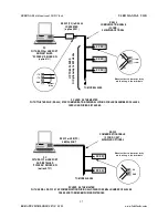
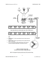
MASTER - SLAVE SYNCHRONIZED SYSTEM CLOCK NETWORKS
A group of SELENA clocks may be installed as SLAVES and a MASTER in a Synchronized Master - Slave System utilizing
one of the following methods of communication:
1.
Power Line Carrier System
with Synchronizing signal carried by the Power Line that is also supplying the power
for the clock. A dedicated Master transmitter must “inject” the sync signal into the power line.
2.
Similar as the Power Line Carrier Sync
protocol only the Sync signal may be either a dedicated wire with High
Voltage ( usually same as the line voltage ) or a Low Voltage (5V to 35V AC/DC) signal.
3.
Serial Communication via the Power Line
usually at 300 or 600 Baud speeds. All sync communication is carried
via the existing Power Line wiring.
A
.
Using the
Standard SELENA Time Sync communication protocol
B.
Using
the
ASCII Time Code Formats “0, 1, 2 or 3”
C.
Using
the
LATHEM compatible protocol ASCII Time Code
4.
Radio Communication
via a dedicated RF Transmitter / Receiver usually at 1,200, 600 or 300 Baud speeds.
A
.
Using the
Standard SELENA Time Sync communication protocol
B.
Using
the
ASCII Time Code Formats “0, 1, 2 or 3”
C.
Using
the
LATHEM compatible protocol ASCII Time Code
5.
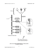
2-WIRE (twisted pair) Sync System
with the Synchronizing signal from the Master clock or a PC, carried by a
Dedicated Cable in
RS232 or RS485
compatible standard with a low voltage sync signal connected to each slave
clock in the network.
A
.
Using the
Standard SELENA Time Sync communication protocol
B.
Using
the
ASCII Time Code Formats “0, 1, 2 or 3”
C.
Using
the
LATHEM compatible protocol ASCII Time Code
6.
MINUTE IMPULSE Sync
System for 2-wire, 3-wire and Reverse Polarity 1 Minute and 1/2 Minute Impulse
7.
BCD Time Code
(Simplex compatible) for 50 and 60 Hz clock speed.
8.
Multi-zone Clock System
9.
Custom
RS-232 or RS-485 compatible communication network at 9600, 1,200(or 4800), 600 or 300 Baud speeds.
See the following sections for the description of each of the above sync systems.
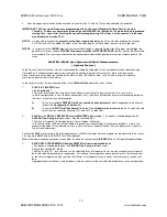
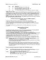
POWER LINE CARRIER Synchronizing signal ( Fn 23 enabled )
( Optional Feature )
Large System Clock installations may be synchronized by injecting a strong, low frequency signal into the power line at certain
times of the day. The Slave Clocks receive that signal and self-adjust their internal circuitry in order to remain “IN-SYNC” with
the Master clock and all other clocks in the system.
Two distinctive types of sync signals are sent with a different purpose:
1.
12 HOUR Sync Mode ( disable Fn 14 )
Sent from 57th minute 54th second to 58th minute 02 seconds of every hour except at 05:57.54 and 17:57.54 when
the signal lasts until 58th minute 08 seconds.
2.
24 HOUR Sync Mode ( enable Fn 14 )
Sent from 57th minute 54th second to 58th minute 02 seconds of every hour except at 05:57.54 when the signal
lasts until 58th minute 08 seconds.
Each clock may be setup to respond to
ANY
SELECTED
sync signal frequency
within the range of the clock model.
Normally this range will be from 2,000 Hz up to 16,000 Hz.
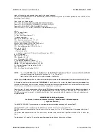
To select a particular Sync Frequency perform the following:
1.
Make sure that functions
Fn23, Fn 31, 38, 39 and Fn 11
are Enabled.
2.
Press the “SET” key on the Remote and select the frequency in multiples of 10x by pressing the “UP” and “DN” keys.
For instance to setup 2925 Hz select the number: 292 .
3.
When the digits stop flashing, press the “SCAN” key to return to the regular time display.


