SELENA
Multifunctional LED Clock
USER MANUAL V32D
KERA TECHNOLOGIES INC. 2013
www.ledclocks.com
29
4.
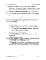
After the frequency selection has been made, the functions Fn 31 and Fn 11 may be disabled or left enabled.
IMPORTANT: The Sync signal Frequency programming affects the current Stopwatch/Timer/Counter memory.
Therefore, if timers or counters are also being used, DISABLE the function Fn11 and renew the programmed
starting time / count after finishing the zone offset programming. If the timer, not the counter is to be used,
also disable the function Fn31.
NOTE1:
It is possible to monitor the
presence of the Sync signal detected
by the Slave Clock by enabling the function
Fn12. When Fn12 is enabled, the colon in the time clock display will flash when the sync signal is present
.
NOTE2:
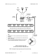
In systems with the
WIRED
Impulse Sync transmitted through a separate Cable, High Voltage or Low Voltage, the
operation is similar except the
SIGNAL Frequency selection is NOT NECESSARY
and the function
Fn 13
must be
also enabled. The sync signal should then be connected to a pair of designated terminals on the back panel of the
clock.
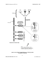
MASTER—SLAVE Sync System with Serial Communication
( Optional Feature )
Large System Clock installations may be synchronized by linking them together in a serial communication network using a
“Twisted Pair“ 2-conductor cable, power line serial communication, Ethernet/Internet or RF ( radio ) communication.
Slave Clocks receive the data transmitted by the Master Clock ( SELENA or other ) or a PC and interpret that data to
synchronize themselves with the Master.
In the simplest system the basic configurations for the
Master-Slave
operation are as follows:
1.
SLAVE
for
TIME SYNC
only
( for all protocols )
The slaves will interpret the Time data from the Master and will set its own internal clock “in sync” with it.
In these configurations, even if the data connection is lost, the Slaves will continue accurate timekeeping based on
the latest, successful sync data reception.
A.
To use the standard
SELENA Time Sync communication protocol
enable the appropriate functions as
listed in the
Configuration Table
below.
B.
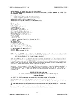
To use the
ASCII Time Code Format “0,1,2 or 3” or Lathem protocol
enable both Fn 34 and Fn 46 and
select the sync format by enabling Fn11 and Fn12 as required.
2.
SLAVE
as the
DISPLAY REPEATER form the MASTER clock screen
( This option is allowed
only
when the
SELENA Time Sync protocol
is used ). See the function
Fn 33
.
The Slave will repeat all the display data as transmitted by the Master.
In this configuration the Slave will not be able to perform any other display functions except when it is put in the
programming mode via the Remote Control. In case of a loss of communication, the slave display may “freeze” at
the last received screen.
The function
Fn33
may be used in Special Applications as the Master display contents repeater for broadcasting to the slaves.
This may work
ONLY
with the SELENA Time Sync protocol.
When other communication protocols are enabled, the clock may automatically
DISABLE
the Fn 33 Display Repeater Mode.
3.
EXTRA DATA TRANSMISSION from the MASTER or from designated Slaves
( This option is allowed
only
when the
SELENA Time Sync protocol
is used ).
See the functions
Fn 81, 82, 83
.
The Master ( or a PC ) or in some cases the selected Slaves or Repeater slaves, may be setup to transmit special
data with selected parameters or commands. For instance the temperature measurement results, the relay control
or the timer setup data may be sent from the Master or the repeater to some slaves that are setup to receive such
data.
Appropriate control software ( and hardware ) and functions must be installed and enabled to use this configuration.


