6
Installation
The radiator may only be installed by a specialist partner.
Conditions of use
Ŷ
Observe the operating conditions for hot water heating
systems as defined in DIN 18380 “VOB German Cont-
ract Procedures for Building Services”.
Ŷ
Maintain water quality as defined in VDI 2035 “Preven-
tion of damage in hot water heating systems”.
Ŷ
Observe the limitations for use in wet rooms as defined
in DIN 55900 “Coatings for radiators”.
Ŷ
Use radiator only in closed heating systems.
Ŷ
Only store and transport radiator in the protective
packaging.
Ŷ
Observe minimum clearances between radiator and
surrounding objects for air circulation.
Ŷ
When installing in rooms with bath or shower facilities:
Take protective areas as per DIN VDE 0100-701 into
account. Also follow all local regulations.
Ŷ
Note: The manufacturer prohibits installation of the
products in safety area 1 and 2.
Technical features
Ŷ
Operating pressure: max. 10 bar
Ŷ
Test pressure: 1.3 x operating pressure
Ŷ
Flow temperature: hot water up to 55 °C (131 °F)
Directions for installation
Protect radiator from damage
Ŷ
When installing, only remove protective packaging at
the fixing and connection points.
Ŷ
Only remove protective packaging completely during
final cleaning or prior to initial operation.
Fixing points
Ŷ
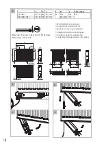
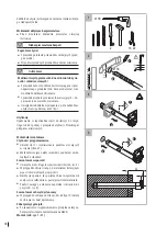
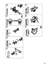
For radiators with lugs: Note the number and positions
of fixing points (see Fig. A).
Ŷ
Install built-into-wall brackets according to separate
installation instructions (see page 15).
Compact radiator connection
Ŷ
Unscrew lacquered blanking plugs at the designated
connection points.
Ŷ
For multilayer radiators and twinwire or alternating
connection: Install accompanying Therm X2
®
separa-
ting plugs (see page 20).
Ŷ
Connect radiator with commercially available fittings
upstream.
Ŷ
Tightly cap open connections with air vent plugs (top)
and blanking plugs.
Only existing blanking plugs may be used on Kermi steel
panel radiators.
Valve radiator connection
Valve, air vent plugs (top), and blanking plugs are factory
pre-installed.
Ŷ
Connect radiator with commercially available fittings
upstream on the valve fitting.
Radiators with two paint caps (FTV/PTV/PLV):
Ŷ
Remove paint caps from bottom on the valve fitting and
dispose of them, as they must not be used as seals on
the radiator.
Radiators with four paint caps (FTP/PTP/PLP):
Ŷ
Remove paint caps from bottom on valve fitting that
connections are being made to. Paint caps are screwed
on are tight and authorized for permanent operation.
Note: After removing the paint caps, check the connec-
tions for any residue. If necessary, clean the connections.
Fan connection
Ŷ
When installing the radiator (fixed installation), an
all-pole disconnection device needs to be provided for
the fan unit according to DIN EN 60335-1.
Ŷ
Ensure that a correctly mounted unit connection box
or wall socket (230 V, 16 A fuse) is available within
the cable range.
Ŷ
The wall emanating electrical connection must be freely
accessible and must not project out to the surface of
the radiator or the control unit. The radiator must not
be attached directly beneath a wall socket.
Warning
Risk of injury!
There are sharp edges inside the radiator.
Ŷ
Be careful when reaching in.
Ŷ
Prepare the mains cable for connection by folding away
the control unit (Fig. C).
Ŷ
Remove the adhesive tape and carefully pull the mains
cable out of the radiator, remove adhesive tape residue
(Fig. D)
Ŷ
Fold the control unit back in until it clicks into place in
the radiator (Fig. E).
Ŷ
Connect the power supply cable.


