PBJ_N-SH-e-1810.docx
42
16.6 Replacing the Assy,Detector (U8)
-
Detach the Assy,Case (3) / Assy,Pan support (4) in accordance with the steps outlined in
“3. Inspection of the Balance Interior”.
-
Disconnect the Cable,65 (U27) connector at the Assy,Analog (B3).
-
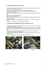
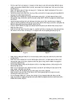
Remove the two P3 M3x10 hexagonal socket-head bolts (U22) that fixes the
Assy,Detector (U8) (Fig.11).
-
Remove the soldering of the temperature sensor cable connected to the Assy,Detector
(U8).
Note: TP1: Yellow wire, TP2: Blue wire
-
Detach the Assy,Detector (U8).
Note: Be very careful when removing it to avoid damaging the elastic support by hitting
the Assy,Lever (U4).
-
Fit the new Assy,Detector (U8) by following the steps 2) to 5) outlined above in reverse
order.
-
Conduct “7.1 Adjustment of the Assy,Detector (U8) Height”.
16.7 Replacing the Weight loader assy (10) (UW series only)
-
Detach the Assy,Case (3) / Assy,Pan support (4) in accordance with the steps outlined in
“3. Inspection of the Balance Interior”.
-
Undo the CS-5 clip (15) securing the Cable,45 (B7) and the Weight loader assy (10) and
disconnect the Cable,45(B7) and Weight loader assy (10) connectors at the Assy,Display
(B4).
-
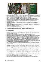
Loosen the four P4 M4x10 screws (23) fixing the Weight loader assy (10) in place to
detach the Weight loader assy (10) (Fig.12).
-
Fit the new Assy,Calibration weight loading (10) by following the steps 2) to 3) above in
reverse order.
-
Perform “6. Adjustment of the Pin Height of the Weight loader assy (10)”.
TP2: Blue wire
10
U8
23
TP1: Yellow wire
U22
Fig.11
Fig.12
Summary of Contents for PBJ-N
Page 4: ...PBJ_N SH e 1810 docx 4 ...
Page 40: ...PBJ_N SH e 1810 docx 40 Fig 7 Fig 8 ...
Page 47: ...47 PBJ_N SH e 1810 docx Fig 22 Fig 23 ...
Page 55: ...55 PBJ_N SH e 1810 docx 23 Drawing Fig 31 ...
Page 56: ...PBJ_N SH e 1810 docx 56 ...
Page 57: ...57 PBJ_N SH e 1810 docx Fig 33 ...

