17
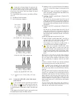
"A"
"C"
"b"
"D"
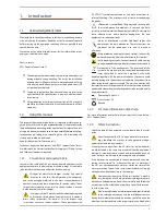
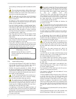
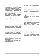
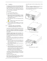
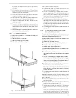
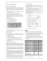
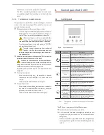
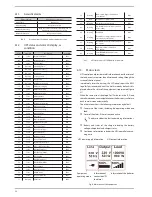
Fig. 6.
Taking out the front cover.
4.2.5.2. Vertical -tower type-assembling
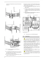
• Rotate the control panel according to section 4.2.5.1.
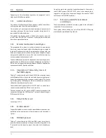
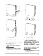
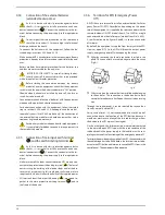
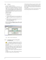
• in equipments up to 3 kVA, take the 4 plastic pieces "A" in angle
shape supplied with the equipment and joint them two by two
till obtain two supports or stabilizers "b".
• For equipments up to 3 kVA.
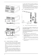
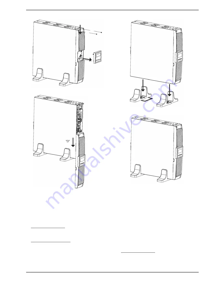
Put the UPS vertical between the two stabilizers supports "b"
(see figure 7).
For equipments of higher power.
Put the equipment vertical and fix the two metallic supports,
one at each side, by means of the supplied screws (models 4
to 6 KVA).
For equipment of 8 to 10 kVA, put the equipment vertical.
There are no supports or stabilizers.
"A"
"A"
"b"
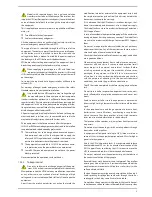
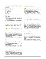
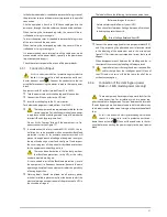
Fig. 7.
Vertical -tower type- assembling.
4.2.5.3. Vertical -tower type- assembling, with
extended back up time (battery module)
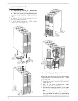
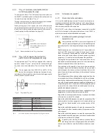
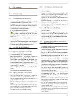
• The description of this section is based on an equipment with
only one battery module (see figure 8). For a higher quantity of
modules proceed to the connection among them.
• Rotate the control panel of the equipment according to section
4.2.5.1.
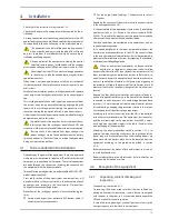
• in equipments up to 3 kVA, take the 4 plastic pieces "A" with angle
shape and supplied with the UPS and the two supplied with the
battery module "b", and joint them till obtain two supports or sta-
bilizers "C" to hold the equipment and battery module.
• For equipments up to 3 kVA.
Put the UPS and battery module on vertical position between
the stabilizers supports "C".
Fix the "D" metallic piece that joint UPS and battery module

