background image

Manual_KESSUPS92RT_V3_ENG

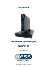
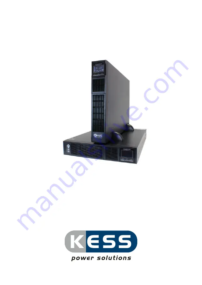
Uninterruptible power supply

KESSUPS 92RT 

1 to 6 kVA

User Manual

Summary of Contents for KESSUPS 92RT

Page 1: ...Manual_KESSUPS92RT_V3_ENG Uninterruptible power supply KESSUPS 92RT 1 to 6 kVA User Manual...

Page 2: ...TERy ModULE 18 5 6 4 MoUNTiNG iN A 19 CAbiNET 19 5 6 5 MoUNTiNG iN A 19 CAbiNET wiTh bATTERy ModULES 20 6 CoNNECTioN of ThE dEViCE 20 6 1 bEfoRE CoNNECTiNG 20 6 2 bEfoRE CoNNECTiNG bATTERiES ANd ThEiR...

Page 3: ...Cd MoNiToR foR ModELS UP To 3 KVA 41 8 2 1 ACoUSTiC ALARMS 42 8 2 2 PARAMETERS foR ThE UPS CoNfiGURATioN 42 8 2 3 SETTiNGS oN ThE UPS diSPLAy 45 8 2 4 MEANiNGS of ThE oPERATioN ModE 48 8 2 5 ERRoRS fA...

Page 4: ...curate we are not responsible for the completeness of contents and accuracy The images included in this document are for illustrative purposes and may not represent exactly the parts of the equipment...

Page 5: ...manner without having any doubts whatsoever finally once the equipment is installed and operating it is recommended to save the documentation downloaded from the website Cd RoM or Pen drive in a safe...

Page 6: ...be necessary to avoid disturbances it is not appropriate to use this equipment in basic life support applications bLS where a failure can render vital equipment out of service or significantly affect...

Page 7: ...3 3 ENViRoNMENT This product has been designed according to iSo 14001 and complies with all essential environmental regulations Recycling of the equipment at the end of its lifespan when it comes to d...

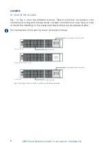
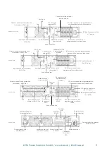
Page 8: ...ight contradictions may arise in case of doubt the labelling on the equipment itself will always be representative The nameplate of the device shows all relevant values Models up to 3 kVA battery modu...

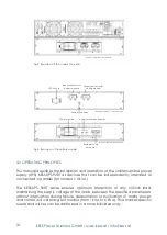
Page 9: ...utput connector non programmable for critical loads Port Com RS 232 Earth connection input connector for Modem AdSL fax output connector with protection for Modem AdSL fax fan input connector for Mode...

Page 10: ...module 4 2 oPERATiNG PRiNCiPLES This manual describes the installation and operation of the uninterruptible power supply UPS KESSUPS 92RT as devices that can be independently operated or connected in...

Page 11: ...e availability of critical loads and to ensure that your business is protected from variations in the power distribution line voltage frequency electrical noise cuts and micro cuts This is the primary...

Page 12: ...y of fast and easy backup extension by adding modules in rack format Each battery module has two connectors for easy connection to the device and other identical modules N X redundant parallel connect...

Page 13: ...tenance or repair operations on the device can be carried out without interruptions to the power supply of the protected system while preventing unnecessary hazards for the technical personnel communi...

Page 14: ...ng cart in any means consider the technical data of the device as described in chapter 9 5 1 dELiVERy 5 2 PACKAGiNG To check the contents it will be necessary to remove the packaging Unpack in the fol...

Page 15: ...tional battery modules for UPS 1 to 3 kVa 1 battery module 2 metal pieces for the use as handles and screws for installing the unit in a rack cabinet 4 plastic pieces for use as a base to facilitate t...

Page 16: ...er with the applicable battery module Start it according to the instructions described in this manual and charge it for 12 hours in parallel systems it is not necessary to interconnect the devices bef...

Page 17: ...ons provide help and guidance in the following steps but the instructions are not intended to refer to a single model Although the carried out actions are in practice always the same for all of them f...

Page 18: ...r 5 6 3 VERTiCAL MoUNTiNG TowER wiTh bATTERy ModULE Rotate the LCd monitor Take the 4 plastic pieces in angle form supplied with the UPS and the 2 angle forms supplied with the battery modu le install...

Page 19: ...can supply universal slides as guides These must be installed by the user Mount the guides at the required height ensure the correct tightening of the fixing screws and the appropriate fitting of the...

Page 20: ...the slides Place the device onto the guides and insert it all the way to the back Repeat the same procedure for the battery module it depends on the device model and weight if it should be installed i...

Page 21: ...cables must always be considered in relation to the size of the terminals and switches so that the cables with their entire cross section are correctly fastened for an optimum contact between the two...

Page 22: ...attery protection of the device and of any accumulator module has to be carried out by internal fuses so that it is not accessible to the user important for your safety if you install the batteries by...

Page 23: ...e the screws and protective cover of the connector before interconnection All battery modules include 2 connectors that enable extended backup times available communication connectors db9 for RS232 Mo...

Page 24: ...ous voltage or power on the UPS input line during a mains failure see fig 9 The standard applies to both individual units as well as parallel systems warning labels should be attached to all primary p...

Page 25: ...aser printers or CRT monitors the starting up of these peripherals will need to be taken into account to prevent the device from crashing we do not recommend connecting loads of this type due to the a...

Page 26: ...line affected by the short circuit As the device has class i protection against electric shock it is essential to install a protective earth conductor connect earth Connect this conductor 6 8 CoNNECTi...

Page 27: ...x 16 192 V 400 32 Tab 1 Protection features between device and battery module Each battery module is independent from each device it is permitted to con nect two devices at one and the same battery m...

Page 28: ...Ger tabwerkmiteinem geschlossenen Notaus Stromkreis EPo geliefert The device is delivered ex factory with its EPo circuit set to closed NC The UPS will cut the output power supply emergency power off...

Page 29: ...igital input digital input fig 12 digital input ouput to the relay connector 6 12 AUxiLiARy CoNTACTS foR ThE MANUAL byPASS oNLy foR ModELS 3 KVA KESSUPS 92RT contains a auxiliary contact it is possibl...

Page 30: ...ode Up to 3 devices can be connected in parallel to configure a shared output or power redundancy Parallel installation and operation The communication line com constitutes a very low voltage safety c...

Page 31: ...aker To the loads manual bypass fig 15 Parallel installation of two UPS systems from 4 to 6 kVA with fuse box and manual bypass Mind the connection procedure for the input as described in paragraph 6...

Page 32: ...imum voltage and current applicable to these contacts is 30V dC and 1A There also is a Shutdown input it enables that the inverter is shut down when this input has a voltage between 10 and 12 V for mo...

Page 33: ...original cover for further information please contact our KESS service Protection against voltage spikes for the modem adSL fax The communications line CoM constitutes a very low voltage safety circu...

Page 34: ...Shut down the connected loads before starting the UPS and start the loads one by one only when the UPS is running it is very important to proceed in the established order if in addition to the more se...

Page 35: ...seconds the audible alarm will sound for 1 second and the UPS will start up depening on the model the fan will start After checking the device the main screen will be displayed for 4 to 6 kVA models i...

Page 36: ...UPS separately to check that the voltage difference between them is less than 0 5 V if the difference is greater than 1 V check the connection and the associated instructions if everything is correct...

Page 37: ...e manual bypass switch which is located at the back of each unit and turn all of the switches to bypass Consider that in bypass mode the loads are exposed to voltage and frequency variations and cuts...

Page 38: ...the manual bypass line Turn the manual bypass switch or disconnector on the distribution board to off and reposition the mechanical lock to prevent possible accidents To prevent incorrect operations i...

Page 39: ...g current charging level information about the load Shows the level of the load 0 24 25 49 50 74 75 100 Shows overload information about programmable outputs The programmable outputs are activated inf...

Page 40: ...mally open AC EPo normally closed EAT Estimated backup time RAT backup time Sd Shutdown oK ok oN on bLn L Low battery oL overload oi input overcurrent NC battery is not connected oC battery overcharge...

Page 41: ...be moved upwards one point activate the battery test Press this button at least 3 sec when the device operates in Normal mode or frequency converter mode Cf After testing the device will return to th...

Page 42: ...alarm models up to 3 kVA 8 2 2 PARAMETERS foR ThE UPS CoNfiGURATioN Parameter 1 Code of the UPS setting mode see Tab 7 Parameter 2 Configuration of value options for each UPS setting mode All paramete...

Page 43: ...h Standard models are configured ex factory so it is not necessary to perform any actions to adjust this parameter however for models with extended backup it is necessary to adjust the value to the ta...

Page 44: ...modules The battery capacity of both are described in Tab 8 and Tab 9 for example a KESSUPS 1500 and a backup extension module KESSUPS EbM 36V 9 Ah 18 Ah 27 Ah value for parameter 12 Model internal b...

Page 45: ...enabled diS bypass disabled No output voltage if the UPS is shut down 07 bypass voltage range Choose the highest and lowest acceptable voltage value for the bypass mode with the Up button and down but...

Page 46: ...lease choose the maximum charging current based on the battery capacity The recommended charging current is 0 1 0 3 of the battery capacity battery capacity current A 7 20 2 20 40 4 40 60 6 60 80 8 80...

Page 47: ...play settings for the backup time EAT Shows the remaining backup time RAT Shows the expired backup time 19 Permitted input voltage range Choose the highest and lowest acceptable voltage value with the...

Page 48: ...ant output frequency of 50 or 60 hz The device will still charge the batteries in this mode battery mode when the input frequency voltage is not within the predefined range of the device or there is a...

Page 49: ...dervoltage 11 inverter soft start fault 12 high voltage in the inverter 13 Low voltage in the inverter 14 inverter output short circuited 27 high battery voltage 28 Low battery voltage 2A battery char...

Page 50: ...t at the connection socket beeps every 2 sec EPo activated beeps every 2 sec overtemperature beeps every 2 sec Charger faulty beeps every 2 sec battery fault beeps every 2 sec The UPS shuts down and w...

Page 51: ...or frequency converter mode Cf After testing the device will return to the respective mode Button to navigate upwards when you press this button in the UPS setting mode the menu will be moved upwards...

Page 52: ...de o battery test o o fault o o o o Tab 14 LEd display with different modes models 4 to 6 kVA 8 3 1 ACoUSTiC ALARMS Meaning alarm tone Possibility to mute UPS state bypass mode beeps every 2 sec yes b...

Page 53: ...y mode Battery test 01 output voltage yes 02 output frequency yes 05 ECo mode enabled disabled yes 08 Settings for the bypass mode yes yes 09 Settings for the maximum time of the battery discharge yes...

Page 54: ...device or there is an AC mains failure the UPS powers the loads from the batteries for a limited time due to their own capacity and activates the audible alarm modulated every 4 seconds bypass mode wh...

Page 55: ...llel communication fault 41 overtemperature 42 CPU communication fault 43 output overload 6A battery start up fault 6b PfC current fault in battery mode 6C dC bus voltage change too fast code Meaning...

Page 56: ...in this manual The life span of the batteries greatly depends on the ambient temperature and other factors such as the number of charges and discharges as well as their depth The life span is between...

Page 57: ...replace any connection cables original materials have to be purchased through our KESS Service or authorised distributors Using inappropriate cables can lead to overheating and fire hazards Inside the...

Page 58: ...with the guide of Tab 21 and Tab 22 if the problems consist please contact our KESS Service Proceed as follows if you contact the service Model and serial number of the UPS date on which the issue occ...

Page 59: ...After repeated overloads the UPS is locked in bypass mode The connected loads are powered directly from the mains disconnect the not needed loads from the output sockets shut down the device and rest...

Page 60: ...and the fault code 43 are shown on the LCd monitor The acoustic alarm beeps continuously The UPS is overloaded for a long time and the device is locked The UPS shuts down automatically disconnect or...

Page 61: ...0 8 10 GEnERaL TEchnicaL SPEcificaTionS Technical specifications KESSUPS 92RT models 1 kVa 1 5 kVa 2 kVa 3 kVa 6 kVa Technology online double conversion PfC double dC bus Rectifier input type Single p...

Page 62: ...ins Mixed thyristors in antiparallel relay Rated voltage That of the mains Rated frequency That of the mains Batteries Element voltage 12 V dC capacity 7 Ah 9 Ah 7 Ah numbe of batteries in series grou...

Page 63: ...oad optional card for the slot interface to relays SNMP remote management via internet and intranet noise level at 1m 50 db 55 db 58 db operating temperature 0 to 40 C Storage temperature 15 to 50 C W...

Page 64: ...64 KESS Power Solutions Gmbh www kess at info kess at KESS Power Solutions Gmbh Gewerbestra e 6 3580 horn Austria 43 720895010 0 info kess at www kess at...

Reviews: