


20
KESS Power Solutions Gmbh / www.kess.at / info@kess.at
•
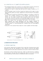
This paragraph refers only to devices with a single battery module. for devices
with a greater number of battery modules proceed in a similar way.
•
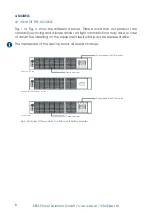
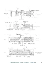
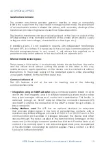
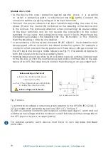
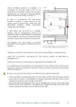
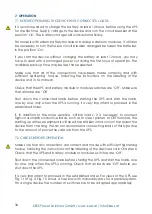
Proceed as in fig. 8 to install the device and its battery module in a 19”
cabinet.
• Use the supplied screws to fi x the 2 angle form adapters as handles on each
side of the UPS. Mind your hands. Repeat the same procedure for the battery
module.
•
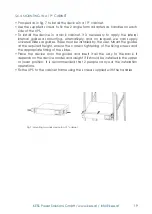
it is necessary to apply the lateral internal guides as mounting to install the
device, UPS or battery modules in a rack cabinet. Alternatively, and on
request, we can supply universal slides as guides. These must be installed
by the user. Mount the guides at the required height, ensure the correct
tightening of the fi xing screws and the appropriate fi tting of the slides.
•
Place the device onto the guides and insert it all the way to the
back. Repeat the same procedure for the battery module. it
depends on the device model and weight if it should be installed in the upper
or lower position. it is recommended that 2 people carry out the installation
operations.
•
fix the UPS to the cabinet frame using the screws supplied with the handles.
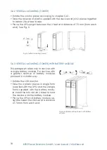
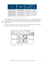
5.6.5 MoUNTiNG iN A 19“ CAbiNET wiTh bATTERy ModULES
fig.8: Mounting in a 19“ cabinet with battery modules
6. connEcTion of ThE dEVicE
6.1 bEfoRE CoNNECTiNG
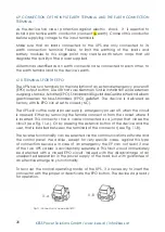
in this manual, references are made to the connection of terminals and switch
operations that are only available in some versions or devices with battery
modules. ignore the described operations if your device does not feature them.
The thermal controls of these devices are carried out with forced air ventilation
from the front to the rear. The front surface and about 15 cm on the rear side
should be left free of obstructions to facilitate the free air circulation.


