


23
KESS Power Solutions GmbH / www.kess.at / info@kess.at
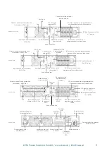
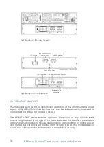
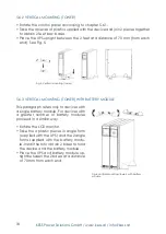
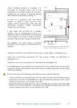
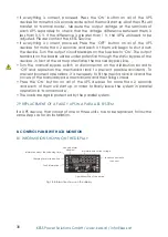
6.3 CoNNECTioN ELEMENTS
All electrical connections of the device are carried out from the back of each
unit:
connection of the input and output:
•
for models up to 3 kVA: input via cable with plug, connectable to the UPS
through an iEC connector. output through iEC connectors.
•
for models with power ratings higher than 3 kVA: Terminals for powering the
device and loads. it is necessary to remove the transparent protective cover to
access the terminals. After connecting, replace the cover to prevent possible
accidents due to direct contact. Especially in tower mountings as there is a
greater risk.
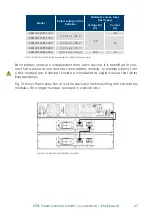
connection of the batteries:
The device and battery module contain a polarised connector. Remove the
screws and protective cover of the connector before interconnection. All
battery modules include 2 connectors that enable extended backup times.
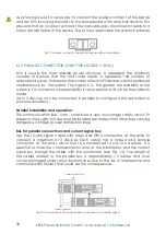
available communication connectors:
•
db9 for RS232. Models up to 3 kVA are supplied with the same connector as
the relay signals.
•
USb to operate the UPS as a PC peripheral device.
•
digital input and output (only models > 3 kVA).
•
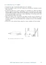
Connection with external EPo button.
•
Auxiliary contact for the manual bypass switch (only models > 3 kVA).
•
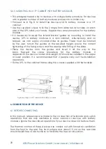
db15 communication bus connectors and analogue current signal block for
connecting systems in parallel (only models > 3 kVA).
it is recommended to use terminals on all ends of the cables connected to the
power terminals (input and output). Check that the terminal screws are correctly
tightened.
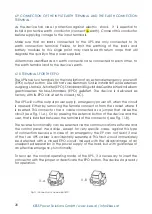
6.4 iNPUT CoNNECTioN
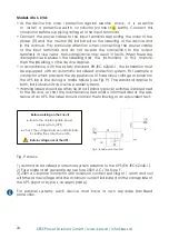
Models 1 to 3 kVa:
•
Take the power cable and iEC connector and insert the latter into the input
connector of the UPS.
•
Plug the power cable into an AC power socket.


