


29
KESS Power Solutions Gmbh / www.kess.at / info@kess.at
6.11 TERMiNALS foR ThE diGiTAL iNPUT ANd oUTPUT To ThE RELAy (oNLy
ModELS > 3 KVA)
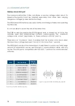
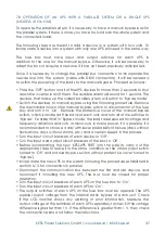
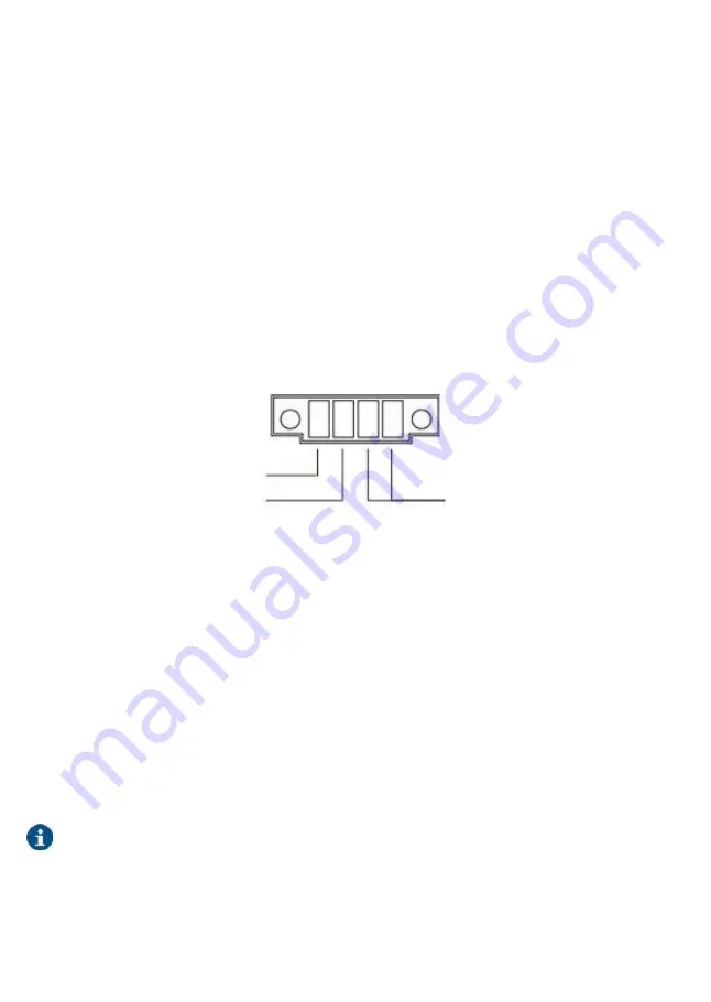
The device contains one connector with four terminals for a digital input and
output to the relay (see fig. 12).
digital input to “Start-Stop“ the device:
when the device is in operation a
sequential voltage between 5 and 12 V dC has to be applied to reverse the
mode. The device contains an internal static bypass ex factory. if the inverter
is shut down, the output terminals will supply voltage trough the internal static
bypass. deactivate the bypass across the panel if the output supply should be
shut down.
Error or fault of the dry contact: Each alarm changes the mode of the normally
opened 24 V dC 1A contac A (No). (Pay attention to the applied voltage and
current!)
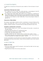
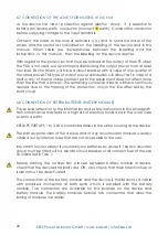
output to the relay,
error or fault
- digital input
+ digital input
fig.12: digital input / ouput to the relay connector
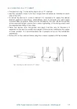
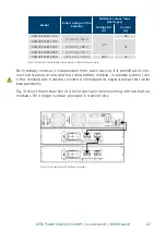
6.12 AUxiLiARy CoNTACTS foR ThE MANUAL byPASS (oNLy foR ModELS > 3 KVA)
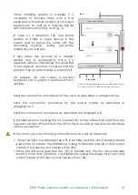
KESSUPS 92RT contains a auxiliary contact. it is possible to activate the shut down
command for the UPS’s inverter when it comes to closing the circuit. This normally
open contact is intended for connection to an external manual bypass switch or
disconnector (see fig. 13).
The connection between the auxiliary contact and the UPS is in parallel. in this
way, any of the auxiliary contacts that close the circuit will activate the shut
down command of the inverter, transferring the powering of the loads to the
internal static bypass, unless this is disabled across the control panel, so that it will
cut the powering of the loads.
in parallel systems, the manual bypass switch of the fuse box or disconnector will
have an auxiliary contact block for each device. Under no circumstances the
different contacts should be joined as this would connect the different earths of
the control of each UPS.


