


38
KESS Power Solutions Gmbh / www.kess.at / info@kess.at
•
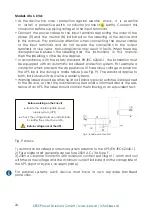
if everything is correct, proceed. Press the ‘oN’ button on all of the UPS
devices for more than 2 seconds and each of them will start up. All of the UPSs will
transfer to ‘Normal mode’. Measure the output voltage at the terminals of
each UPS separately to check that the voltage difference between them is
less than 0,5 V. if the difference is greater than 1 V, the UPSs will need to be
adjusted. Please contact the KESS Service.
•
if everything is correct, proceed. Press the ‘off’ button on all of the UPS
devices for more than 2 seconds and each of them will begin to shut down
the device. Turn the output circuit breakers on the fuse box to ‘on’. The output
terminals on the board will be under potential through the static bypass of the
devices, in fact at the same potential as the manual bypass line.
•
Turn the manual bypass switch or disconnector on the distribution board to
‘off’ and reposition the mechanical lock to prevent possible accidents. To
prevent incorrect operations, it is necessary to fi t the mechanical lock and the
covers of the manual bypass mechanisms and their fi xing screws.
•
Press the ‘oN’ button on all of the UPS devices for more than 2 seconds
and each of them will start up, in order to fi nally leave the system in parallel
operation in ‘Normal mode’.
•
The loads are again protected by the parallel system.
7.9 REPLACEMENT of A fAULTy UPS iN A PARALLEL SySTEM
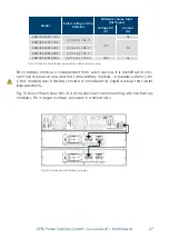
if a UPS device, that consist of one or three units, has to be replaced, follow the
same steps as for an installation.
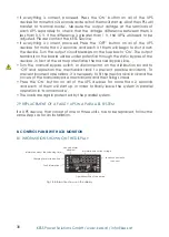
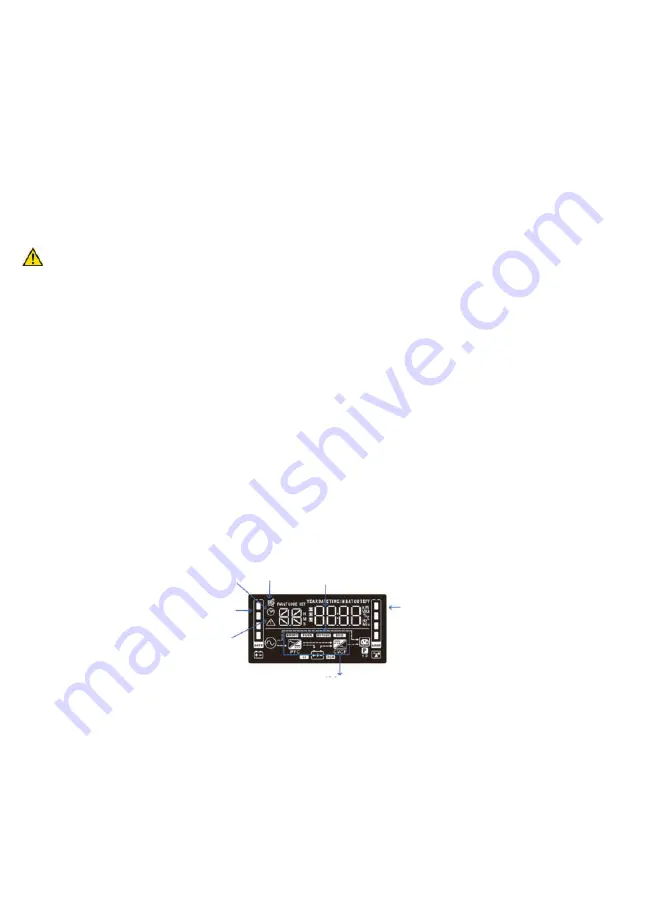
8. conTRoL PanEL WiTh Lcd MoniToR
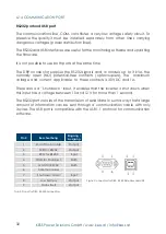
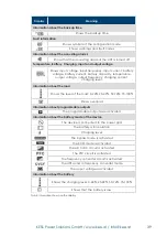
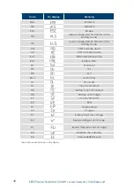
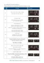
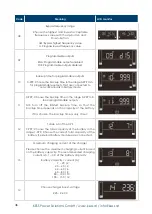
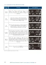
8.1 iNfoRMATioN ShowN oN ThE diSPLAy
fig.18: information shown on the display
Charging level of the battery
fault information
information about the unloading time
Acoustic alarm
disabled
information about the voltage
operation mode of the device
Loads connected to
the ouput


