background image

889012120 0000  Page 26 of 27 

Check if you can move the fitting up and down with the handset. If yes, are the sliding switches at 

     sender and receiver in the same position? (See page 23 for adjustment of send and receive channels.)      

Make sure that the IR receiver is not covered.

Are the handset TMU 10 and the IR receiver connected with the correct jack? (See page 22.)

Is the safety sensor plugged in? (If the scope of delivery does not include a safety sensor, this point is

     irrelevant.) 

Is the power cord correctly plugged in at the control?

Is the power cord correctly plugged in at the mains?

Is the socket live and is it switched on?

If the failure continues, please inform your service partner.

2. Control unit does not work, acoustic signal (beeping tone) can be heard

The control unit must be reset first. (See page 23 for how to reset the control unit)

If a reset is not successful, the following reasons can apply:

- The control unit is in it`s starting-up phase, e.g. fitting has been moved for more than two minutes. Fitting will pause for 18 min. 

  Try again after the pause.


Check if the cild-proof lock is activated.

-  Please check the plug connections.

-  Should a power outage occur whille moving, the control unit must be reset anew (See page 23 for how to reset the control unit.)

If the control unit still does not work please inform your service partner.

Troubleshooting 


1. Remote control does not work; General check 

       -  

Red LED on the infrared remote control does not light up while a key is pressed? 

           Check if battery has been inserted correctly, otherwise you may have to replace the battery!  
           If the LED does not light up after battery has been replaced, the remote control is defective.  
           Please call your service partner. 

 - The red LED on the infrared remote control lights up when key is pressed and the control unit  
    does not make a one-tone sound but there is no function? 

          Execute the following checks: 

3. SME starts to move and immediately stops 

Reset the control unit (See page 23 for how to reset the control unit.) 

o The IR receiver may be covered. 
o Check the IR receiver’s plug connection and all other plug connections if necessary. 

o If the failure continues, please inform your service partner. 


4. SME can only be moved with the handset, not with remote control 

o Check if the channel settings of IR receiver and infrared remote control are in accordance. 
    (See page 23 for adjustment of send and receive channels.)      
o Please check if the IR receiver is covered. If yes, remove cover.


o If the failure continues, please inform your service partner. 

Summary of Contents for ScreenMotion Basic 680

Page 1: ...ScreenMotion Basic 680 720 870 Montageanleitung Assembly Instructions 889012120 0000 Seite 1 von 27 15 06 2009 ...

Page 2: ...ns and legal provisions that are applicable including those that apply in the operator s country as well as the applicable environmental protection regulations The regulations of trade associations or other supervisory authorities that are in force locally must always be observed 8 The manufacturer cannot be held responsible for any losses or damage resulting from unauthorised modifications to the...

Page 3: ...for operation of the control unit must not go below 5 C or above 35 C For these reasons do not assemble the control unit above or in front of heat sources e g heaters in places exposed to direct sunlight behind curtains in small unaired damp rooms on or near easily flammable materials or near high frequency equipment e g transmitters radiationequipment or similar devices If the device emits smoke ...

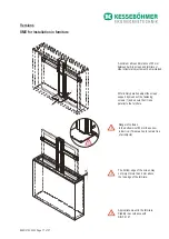
Page 4: ... screen may not project more than 4 mm above the top edge of the furniture Appropriate mount in the furniture Stability in accordance with DIN Fb 147 Versions After initial operation adjust the screen support by means of the fastening screws 1 and ensure that it runs parallel to the furniture 1 1 Danger of collision In the bottommost 80 mm the sensor is inactive This area has to remain free of all...

Page 5: ...not be used a plate of the same size having a minimum weight of 22 kg must be mounted Attention Set screws must be adjusted on a plane surface Item no for the ground plate 889010903 889012120 0000 Page 18 of 27 1 1 Danger of collision In the bottommost 25 mm the sensor is inactive This area has to remain free of all objects 30 708 748 898 ...

Page 6: ...port arms by means of the 4 M6x16 screws and the SW4 allen key to the desired height Remove 4 x M6x30 from the guide column and connect base plate with the 4 screws and the Torx 30 Mounting of support arm Assemble or disassemble only when column is in a lying position 1 x TORX 30 max 15 Nm 4 x 1 x A Fasten fleece tape over the guide column 889012120 0000 Page 19 of 27 ...

Page 7: ... the arms Adjust screen supports with M5x10 and screw driver Tightly screw down M6x12 at the supporting arms Attention Optional mounting to ground plate M6 4x 12x6 4 M6x25 4x M6x25 12x6 4 M6 Mount base plate with 4 M6x25 screws to the ground plate as shown in the illustration 2 x 2 x 4x 889012120 0000 Page 20 of 27 ...

Page 8: ...Connecting the control unit 889012120 0000 Page 21 of 27 ...

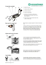
Page 9: ...ut function C Jack for tabletop handset TMU 10 D Jack for IR receiver SME E Jack for safety sensor F Jack for outlet socket with IEC connector G Jack for mains plug Control unit SME Handset TMU 10 up down IR Receiver SME IR Remote control up down Switched mains socket Country specific Mains connection cable D C G F ...

Page 10: ...hannels In order to operate two devices independently of each other they can be adjusted to function on 2 different send and receive channels A and B See fig F2 For the purpose of selecting send and receive channels A and B there are two sliding switches located in the battery compartment or the handset and at the front end of the IR receiver Please make sure that the sliding switch in the IR hand...

Page 11: ...the upward movement of the fitting The SME is pre adjusted to reach the maximum lifting position by the manufacturer If you want the fitting to stop at a position lower than the maximum lifting position move it to the desired position by means of the arrow keys Up and Down Now press the key S three times followed by pressing the Up key one time This position is now saved which the control unit wil...

Page 12: ...m above the bottom position If the ScreenMotion is moved to at least 80 mm below the top position maximum lifting position or lifting limit the power supply remains activated If the ScreenMotion is not completely extended e g only halfway the control unit deactivates the power supply for safety reasons after one minute Thus heat accumulation and any damages to the device resulting from it are prev...

Page 13: ...r outage occur whille moving the control unit must be reset anew See page 23 for how to reset the control unit If the control unit still does not work please inform your service partner Troubleshooting 1 Remote control does not work General check Red LED on the infrared remote control does not light up while a key is pressed Check if battery has been inserted correctly otherwise you may have to re...

Page 14: ...one second after the start of any movement After the safety sensor is activated a pause of ca 5 sec needs to be observed until the swaying of the fitting stops 6 Column remains in extended position For maintenance reasons the column remains extended after 10000 lifts Please call your service partner Subject to change without notice Kesseböhmer Ergonomietechnik GmbH Siemensstrasse 6 D 73235 Weilhei...

Reviews: