background image

e300i User Manual 

Document #: 0503M01A 

       REV : 1.3 

Approval: 

Date:   March ’08 

Page 5 of 25 


2.3 

2.3 

2.3 

2.3 Applications

Applications

Applications

Applications and Uses

 and Uses

 and Uses

 and Uses    

The e300

iiii

 is suitable for electrical power generation on various installations that include battery 

charging,  water  delivery  and  grid  tie  applications.  Each  application  requires  specific  additional 

electrical equipment. Consult the manuals supplied with this equipment. 


2.

2.

2.

2.4

4

4

4 Charge Contr

 Charge Contr

 Charge Contr

 Charge Controllers

ollers

ollers

ollers and Inverters

 and Inverters

 and Inverters

 and Inverters    

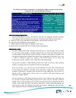
Any  wind  turbine  produces  uncontrolled  power  that  varies  with  incident  wind  speed.  The  open 

circuit  generator  voltage  is  directly  proportional  to  generator  speed  (rpm).  Some  form  of 

regulator  must  control  this  “raw  power”.  A  battery  charging  regulator  is  often  referred  to  as  a 

charge controller. 


A charge controller is required for the Kestrel to charge a battery. Kestrel can supply a standard 

charge controller for the e300

iiii

. A suitable diversion


resistor is available from Kestrel. 


An  inverter  can  be  connected  to  the  battery  and  is  used  to  convert  the  battery  dc  power  to  ac 

power.  An  inverter  therefore  allows  the  use  of  standard  electrical  equipment  that  works  on  ac 

voltage. 


2.

2.

2.

2.5

5

5

5    Grid Tied Inverter

Grid Tied Inverter

Grid Tied Inverter

Grid Tied Inverter Applications

 Applications

 Applications

 Applications    

The 200Vdc version of the e300

iiii

 is suitable for connection to an approved Grid Tie Inverter. Grid 

Tied  installation  is  subject  to  local  electrical  codes  of  practice  and  is  usually  carried  out  by 

qualified  personnel.  Prior  approval  from  the  local  utility  company  must  be  obtained  before 

connection to the mains. 


2.

2.

2.

2.6

6

6

6 Voltage Limiter

 Voltage Limiter

 Voltage Limiter

 Voltage Limiter    

Grid  tied  applications  require  a  Voltage  Limiter  to  be  connected  between  the  e300

iiii

  (200Vdc 

version) and the Grid Tie Inverter. Certain operating modes of the inverter allow the Kestrel output 

voltage to rise beyond the limit of the inverter. The Kestrel Voltage Limiter will restrict the rise in 

voltage as the inverter performs various functions. Refer to the manual provided with the Kestrel 

Voltage Limiter.  


Summary of Contents for e300i

Page 1: ... Approval Date March 08 Page 1 of 25 Registration Number 2006 005438 07 VAT Registration Number 4870231406 Tel 27 0 41 401 2500 Website www kestrelwind co za User Manual Revision 1 3 03 08 Revision 1 2 12 07 Revision 1 1 08 07 Revision 1 0 06 07 ...

Page 2: ... Assembly Tail Assembly Tail Assembly Tail Assembly 9 9 9 9 3 8 3 8 3 8 3 8 Fitting the Pitch Control Fitting the Pitch Control Fitting the Pitch Control Fitting the Pitch Control 10 10 10 10 3 9 3 9 3 9 3 9 B B B Blade Assembly lade Assembly lade Assembly lade Assembly 1 1 1 11 1 1 1 4 4 4 4 Site Considerations and Mountings Site Considerations and Mountings Site Considerations and Mountings Site...

Page 3: ...t for this wind turbine Always short the output wires together when the e300i i i i is disconnected Do not work on the system when the turbine is running or when lightning is possible Disconnecting a running e300i i i i may cause a spark and the presence of explosive hydrogen from battery charging is always a possibility Adequate ventilation must be provided for battery installations The wire size...

Page 4: ...equency output is internally rectified to give a dc output with extremely low ripple content The generated power is transferred to the output cables via heavy duty bronze slip rings and twin copper composite electrical brushes The prime mover on the e300i i i i is a 3 0m 9 85 diameter three blade wind rotor fitted with quiet running high efficiency blades The blade hub incorporates passive pitch c...

Page 5: ...the e300i i i i A suitable diversion resistor is available from Kestrel An inverter can be connected to the battery and is used to convert the battery dc power to ac power An inverter therefore allows the use of standard electrical equipment that works on ac voltage 2 2 2 2 5 5 5 5 Grid Tied Inverter Grid Tied Inverter Grid Tied Inverter Grid Tied Inverter Applications Applications Applications Ap...

Page 6: ...BINE ASSEMBLY 3 UNPACKING AND TURBINE ASSEMBLY 3 UNPACKING AND TURBINE ASSEMBLY 3 1 Com 3 1 Com 3 1 Com 3 1 Components Supplied ponents Supplied ponents Supplied ponents Supplied The following components are supplied Pitch hub assembly Shaft drive key Propeller blade set Generator assembly Tail boom two pieces Tail two pieces Tail Stabiliser two pieces Nacelle cover Nosecone All fasteners and bolt...

Page 7: ... 2 024 30957 Hex Bolt M6x1x80L S Steel 5 023 30830 Top Tail Plate 1 022 30091 Hex Nut Nylock M6x1 S Steel 13 021 30925 Nacelle 1 020 30769 Tail Boom 1 019 30925 Nacelle Cover Plate 1 018 30149 Screw M5x16 C Head S Steel 4 017 30088 Bolt Hex M8x30L S Steel 4 016 30095 Nut Hex M8 Nylock S Steel 7 015 30096 Washer Plain Metric 8mm S Steel 7 014 30022 e300i Generator Assembly 1 013 30173 Nut Hex M12x1...

Page 8: ...E M10 X 35 60Nm 44 3 ft lb BLADE BOLT M12 x 80 S S WITH M12 NYLOCK NUT 35Nm 25 8 ft lb TAIL BOOM M8 BOLTS S S 30Nm 22 1 ft lb M8 NYLOCKS 25Nm 18 4 ft lb NACELLE SCREWS M6 x 16 S S 3Nm 2 2 ft lb M5 x 15 S S 3Nm 2 2 ft lb TAIL BOLTS M6 x 60 S S WITH M6 NYLOCK NUT 10Nm 7 4 ft lb MOUNTING BOLTS M8 x 25 8 8 HI TENSIL PLATED 35Nm 25 8 ft lb 3 5 G 3 5 G 3 5 G 3 5 Generator Assembly enerator Assembly ener...

Page 9: ...le cover to the rear of the generator with the two M6 screws to the required torque setting see 3 4 Pg 7 Slide the front closing plate between the underside of the generator and the nacelle cover and secure with the four M5 screws to the required torque setting see 3 4 Pg 7 through the holes provided Fasten the tail 07 upper and lower halves to the boom with the ten stainless bolts 23 stainless fl...

Page 10: ...generator shaft with a cable tie Remove cable tie before fitting pitch control Smear waterproof grease 30 over the shaft and insert a little inside the front of the generator where the shaft projects out Offer the pitch control hub to the shaft and slide it onto the shaft Using a hexagon key fit the front shaft bolt 15 and washer 14 to the spring locking washer provided into the generator shaft an...

Page 11: ...s be equally spaced when fitted Please follow the instructions given below a Support the generator 02 such that the blades can be fitted to the pitch hub 03 b Fit two blade bolts 11 through a blade compression plate 09 such that they face toward the generator Now fit the first blade 08 on to the bolts and offer the blade from the front to one blade mount Fit the two Nylock nuts 13 on to the blade ...

Page 12: ... as high as possible All obstructions add to possible turbulence which will cause undue stress on the unit and reduced performance Wind speed increases with height above the ground The power in the wind is a cubic function of wind speed Doubling the wind speed increases the power by eight times 4 1 Flange Mounting Detail 4 1 Flange Mounting Detail 4 1 Flange Mounting Detail 4 1 Flange Mounting Det...

Page 13: ...structure must be directly earthed for lightning The power cable is usually brought down the inside of the mounting structure to give some protection Supply cables should never be spanned or suspended from the turbine structure and should be buried at least one half metre deep in a suitable plastic or steel conduit 5 2 5 2 5 2 5 2 Lightning protection Lightning protection Lightning protection Ligh...

Page 14: ... accounted for The power cable should be run down the inside of the pole or structure and then buried in a suitable underground conduit at least 500mm below the ground surface Wire Size for 12V e300i i i i 65A maximum current 10m 33 20m 66 50sq mm 0 85sq mm 000 Wire Size for 24V e300i i i i 35A maximum current 10m 33 20m 66 30m 96 40m 130 50m 165 16sq mm 5 35sq mm 2 40sq mm 1 70 sq mm 00 85 sq mm ...

Page 15: ...er supply 100A of current for 1hr There is much literature available on this subject It is recommended that the e300i i i i should be charging at least 200Ah of battery capacity for a 12V system 6 6 6 6 1 Lead Acid Batteries 1 Lead Acid Batteries 1 Lead Acid Batteries 1 Lead Acid Batteries These are the most popular choice of battery type and can be vented flooded Water may be added or semi sealed...

Page 16: ... at 11m s 24Vdc 900W Rated power at 11m s 12Vdc 850W Annual energy capture at 5m s average 200Vdc 2160kWh Annual energy capture at 5m s average 48Vdc 2060kWh Annual energy capture at 5m s average 24Vdc 1940kWh Annual energy capture at 5m s average 12Vdc 1790kWh For average wind speed of 5ms 1 and 12m tower at sea level Rated sound level 50dB Cut in wind speed 2 5ms 1 Cut out wind speed N A Maximum...

Page 17: ...00i User Manual Document 0503M01A REV 1 3 Approval Date March 08 Page 17 of 25 7 2 7 2 7 2 7 2 DECLARATION OF C DECLARATION OF C DECLARATION OF C DECLARATION OF CONFORMITY ONFORMITY ONFORMITY ONFORMITY 17 ...

Page 18: ...egrees into the wind The charge controller is defective Other connected equipment is defective Disconnect the e300i i i i from the equipment and check that the blades rotate easily There is a short within the turbine generator In very light wind the e300i i i i may well not rotate This is quite normal as there is no useful power in such a light wind and bearing life is greatly extended On older ma...

Page 19: ...tes require more frequent installation checks WARNING Pitch Control The pitch control mechanism is a factory assembly and is not user serviceable Specialist tools and knowledge is required to carry out any maintenance or repair procedures Do not make any unauthorized adjustments or modifications to any part of this assembly Do not force or twist the blades other than gently when checking for wear ...

Page 20: ...l checks on all other electrical equipment Maintenance Tips Maintenance Tips Maintenance Tips Maintenance Tips The pitch control hub should be checked in the following way Visually inspect the unit Check for any stress cracks broken or cracked springs and or corrosion Use gentle pressure to twist the blade in both directions There should be virtually no movement or slackness Push and pull the blad...

Page 21: ...installation maintenance and use in accordance with the User Manual 2 This warranty is further subject to the Customer returning the defective Turbine at its cost to the premises of Eveready within the warranty period and furnishing full details in writing of the alleged defect 3 Eveready s obligations under this warranty shall be limited to the repair or replacement of defective Turbines at its c...

Page 22: ...P O Box 3191 Eveready Diversified Products Pty Ltd North End Eveready Road Port Elizabeth Struandale 6056 North End Eastern Cape Port Elizabeth Republic of South Africa South Africa Tel 27 0 41 401 2500 Email kestrelwind eveready co za Registration Number 2006 005438 07 VAT Registration Number 4870231406 Web www kestrelwind co za 22 ...

Page 23: ...e300i User Manual Document 0503M01A REV 1 3 Approval Date March 08 Page 23 of 25 NOTES NOTES NOTES NOTES 23 ...

Page 24: ...e300i User Manual Document 0503M01A REV 1 3 Approval Date March 08 Page 24 of 25 NOTES NOTES NOTES NOTES continued continued continued continued 24 ...

Page 25: ...Customer Information Customer Information Customer Information Customer Name Postal Address Turbine Number Phone Number E Mail Address Fax Number Enquiry Details Enquiry Details Enquiry Details Enquiry Details Complete the form and submit to Kestrel Wind Turbines Your feedback and queries are valuable to us Indicate your enquiry or feedback in the space provided below For OFFICIAL Use Only Date Re...

Reviews:

Related manuals for e300i