background image

53

Display

Operating instructions

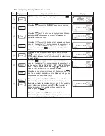
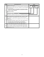
Completion of measurement
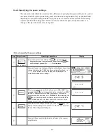
Measuring will be completed when the conditions specified for automatic halting
mode have been met. When measuring is completed, the bias will be displayed
in the bias display area.

*

If no predicted measurement is displayed even after 30 minutes has elapsed

from the time when measuring was initiated, it is probable that it is impossible

to obtain a predicted measurement.

[Measurement results]

Predicted measurement

Automatic halting mode measurement
Bias + 0.60

 = 16.40 (Automatic halting mode value) – 15.80 (Predicted measurement)

Without changing any of the conditions used in steps 

1

 through 

5

, repeat

steps 

6

 through 

8

 to measure again 5 times or more and calculate the

average bias.
The average bias may then be used to specify the bias to be used in predictive
measuring mode.

*

If the bias varies greatly from one time to the next when performing repeated

measurements, then it is probably safe to assume that a predicted

measurement cannot be obtained. If this happens you should measure in

automatic halting mode or in some other mode instead of predictive.

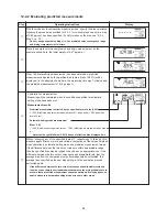
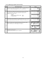
If you wish to use the calculated bias to evaluate predicted measurements,
follow the procedure described in “12-2-2 Evaluating predicted measurements”
on p. 54; if you wish to use the calculated bias to actually obtain predicted
measurements, follow the procedure described in “12-2-3 Obtaining predicted
measurements” on p. 55.

Step

8

9

0

Summary of Contents for FD-720

Page 1: ...Infrared Moisture Determination Balance FD 720 Operating Manual ...

Page 2: ......

Page 3: ...Disconnect Plug Hazard Disassemble to Water Action from Electrical Outlet Do not attempt to measure samples which may undergo dangerous chemical reactions when heated as doing so may result in an explosion or release of toxic gas Do not place flammable materials near the infrared moisture tester Some parts of the infrared moisture tester become extremely hot during operation and could lead to a fi...

Page 4: ...onduct Measurements 19 9 Specifying Measuring Conditions 23 9 1 Types of Settings 23 9 2 Descriptions of Individual Measuring Condition Settings 23 9 2 1 Selecting the CONDITIONS Measuring conditions storage area 24 9 2 2 Selecting the MODE Measuring mode 25 9 2 3 TEMP Drying temperature 34 9 2 4 Bias 35 10 Menu Settings 36 10 1 Types of Menu Settings 36 10 2 Descriptions of Individual Menu Items ...

Page 5: ...urements 54 12 2 3 Obtaining predicted measurements 55 13 Printing Output to a Printer Option 56 13 1 Sample Printer Output 56 13 2 Outputting Past Measurement Data 59 14 Computer Interface 60 14 1 RS 232C Interface Specifications 60 14 2 Setting Up and Transmitting Data 61 14 2 1 Connecting the RS 232C cable 61 14 2 2 FD 720 settings 61 14 2 3 Starting up the computer 61 14 3 Computer Output Form...

Page 6: ...asurements using hazardous materials Heating materials which would present a risk of explosion or combustion or materials which could give off noxious fumes when heated is extremely dangerous and this instrument should never be used with any such materials The same also applies to the use of any materials which might cause hazardous chemical reactions to take place when heated When heating materia...

Page 7: ...keys together at the same time unless directed to do so When there is any danger that the unit might be damaged by lightning remove the power plug from its socket Stopping operation The key can be pressed at any time during operation to halt operation If you suspect for any reason that the product is not operating properly or that there is any sort of danger immediately press the key to halt opera...

Page 8: ... halting mode high speed drying mode low speed drying mode stepped drying mode and predictive measuring mode which makes it possible to perform measurements under the drying conditions most appropriate to the drying characteristics of the sample being measured The ability to store measuring conditions The FD 720 provides 10 measuring conditions storage areas which may be used to store sets of meas...

Page 9: ...y be set within a range of 30 180 C in 1 degree increments Display Backlit LCD display 137 x 43 mm External output RS 232C interface Communications Data may be output from the Data Logger software KDL 01 sold separately or similar software Storage of measurement conditions Allows for storage of 10 sets of measurement conditions Data memory Allows for storage of 100 sets of data Environmental condi...

Page 10: ...s of Parts of Main Unit Handle Observation window Temperature sensor Heater lid Display Level Heater Wind shield Sample dish Sample dish handler Control panel Power conversion switch Power switch Power inlet Fuse holder RS 232C port Height adjustment legs ...

Page 11: ...dish tray Spoon spatula set Spare T8A 250V fuses 2 Power cord Three prong plug adapter Operating manual Packages of aluminum foil sheets 10 per package 2 Note The shape of the power plug varies in different countries The actual accessory may be different from the one in this illustration ...

Page 12: ...play the currently selected measuring mode Used to display the conditions for convergence of measured values when operating in predictive or comparative mode When operating in high speed drying mode used to display the conditions required in order to maintain a high speed drying temperature Used to display the currently selected halt conditions When the value is displayed as a percentage it indica...

Page 13: ...used to return to display of weight after completion of measurement Used to confirm currently selected settings When further settings must be specified pressing the ENTER key causes the next specified item to be displayed when there are no further settings to be selected the specified setting is confirmed and takes effect Used to select different settings or setting values Used to change the value...

Page 14: ...use it in a closed installation environment Depending on the sample heating may produce hazardous substances Install it in a location that can be adequately ventilated 4 Checking the power settings Check the power conversion switch located on the rear of the main unit to make sure that it is currently set to the proper voltage setting for your power source Note that an error will occur if this swi...

Page 15: ...und hole of the sample dish tray fit smoothly over the stay on the sample dish panel 6 Installing the wind shield Open the lid of the heater hold the wind shield by the knobs on the top and place it on top of the sample dish panel so that the two round holes in the wind shield fit over the stays of the sample dish panel Place the wind shield firmly into position so that it does not come into conta...

Page 16: ...ower cord set suited to the shape of the plug that you actually use Connecting the printer sold separately If you are using a printer connect the printer using the provided printer interface cable For instructions on how to use the printer see the separately provided VZ 330 Printer User s Manual Assembly is now complete Some parts must be oriented in a fixed direction for assembly Note that placin...

Page 17: ...culate and viscous sample materials The easier it is to heat the surface of a sample material the easier it is for projecting portions of the material or for material at the top of a mound of material to become burnt If the material is placed in a mound on the dish or if the material is not flat and evenly laid out this is likely to happen thus making it impossible to obtain accurate measurements ...

Page 18: ...nly takes longer for drying to completed to the center but also may result in problems such as the surface of the sample becoming burned thus making it impossible to obtain accurate measurements For this reason you should always crush samples to an appropriate size The TQ 100 Sample Crusher sold separately is excellent for this purpose TQ 100 Sample Crusher ...

Page 19: ...the tester in Japan the settings should be left unchanged Check to make sure that the display reads 100V and then press the key As the power setting continues to be displayed in the lower left of the display the center of the display will change to display CHE4 CHE3 CHE0 and a tone will sound and the display will change to weight reading display mode When the power is turned on for the second or s...

Page 20: ...sample as flatly as possible into the tester so that heat is applied evenly to the sample during measurement See 7 Tips on how to ensure accurate measurements on p 17 for further information 6 Beginning measurement Close the lid of the heater check to make sure that the stability indicator is being displayed and then press the key The display will switch from a display of the weight i e grams to a...

Page 21: ...or once every 30 seconds when near the end of the measuring time while measuring moisture content To stop measuring when in the midst of a measuring operation press the key 8 Completion of measurement When the measuring operation has been completed the heating indicator will disappear the measurement completed indicator will be displayed and a tone will ring for a period of 10 seconds To turn off ...

Page 22: ...ed before proceeding to the next measurement You should also keep a spare cooled sample dish available to use in the next measurement See 7 Tips on how to ensure accurate measurements on p 17 for further information When ready return to step 3 and begin the next measurement Turning off the power When all the measurements have been completed pull the power plug from the power outlet And when not us...

Page 23: ...tive measuring mode on p 32 In predictive measuring mode the intermediate results of drying are used to predict future changes and to calculate the predicted measurement and thereby shorten the amount of time used in measurement For further information see 9 2 2 7 Specifying settings for PREDICT Predictive measuring mode on p 33 This parameter may be used to specify the drying temperature The temp...

Page 24: ...s been specified the message PASS will be displayed to indicate that a password should be entered Follow the instructions in 10 2 7 Specifying a password on p 46 to enter the password The CONDITIONS display area will begin to flash Press the key This will cause the highlight to move to the measuring conditions area number and for the measuring conditions area number to begin to flash Press the key...

Page 25: ... press the key If a password has been specified the message PASS will be displayed to indicate that a password should be entered Follow the instructions in 10 2 7 Specifying a password on p 46 to enter the password The CONDITIONS display area will begin to flash Press the key until MODE begins to flash With the MODE display area flashing press the key This will cause the highlight to shift to meas...

Page 26: ... until MODE begins to flash With the MODE display area flashing press the key This will cause the highlight to shift to measuring mode selection and for the currently specified measuring mode to begin flashing Press the key until TIM begins to flash If TIM is already flashing then proceed directly on to the next step When TIM begins to flash press the key This will cause the measuring time setting...

Page 27: ...emperature Specifying a relatively low degree of change in moisture content or specifying a high rapid drying temperature may reduce the amount of time required to perform a measurement but depending on the sample material being measured doing so could result in the material becoming burnt or make it impossible to obtain accurate measurements Conversely specifying a relatively high degree of chang...

Page 28: ...o the specification of the halting conditions and the numerical field begin to flash Press the key or key to select the desired halting conditions In this example timed halting 20 minutes is specified When the desired time or percentage flashes press the key The temperature field with a value of 180 C or the rapid drying temperature last specified will begin to flash The initial default values is ...

Page 29: ... until SLW begins to flash If SLW is already flashing then proceed directly on to the next step When SLW begins to flash press the key The highlight will then shift to specification of low speed drying mode settings where the halting conditions must be specified The units area for timed halting mode min or automatic halting mode will begin to flash Pressing the key will cause the units to switch b...

Page 30: ...hing press the key This will cause the highlight to shift to measuring mode selection and for the currently specified measuring mode to begin flashing Press the key until STP begins to flash If STP is already flashing then proceed directly on to the next step When STP begins to flash press the key This will cause STP to change from a flashing to a constantly lit display for the highlight to shift ...

Page 31: ...it is impossible to perform continuous measurement over 12 hours in this mode The maximum drying time for each step is 240 minutes When the desired halting conditions begin to flash press the key This will the display of the halting conditions to change from a flashing to a constantly lit display for the highlight to shift to the specification of the drying temperature for Step 2 and for the dryin...

Page 32: ...ill change from a flashing to a constantly lit display and you will next be required to specify the predicted value convergence range settings see Predicted value convergence range on p 50 The current setting for the predicted value convergence range will begin to flash Press the key or key to specify the desired value A value of anywhere from 0 1 to 9 9 percent may be specified in 0 1 percent inc...

Page 33: ...e MODE display area flashing press the key This will cause the highlight to shift to measuring mode selection and for the currently specified measuring mode to begin flashing Press the key until PRD begins to flash If PRD is already flashing then proceed directly on to the next step When PRD begins to flash press the key PRD will then change from a flashing to a constantly lit display and you will...

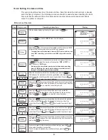
Page 34: ... result in the sample becoming burned thus making it impossible to obtain accurate measurements Note that the meaning of the term drying temperature as it is specified here differs from that of the drying temperature for earlier models e g the FD 600 620 100 230 240 Key s used Operating instructions With the display displaying the weight in grams press the key If a password has been specified the ...

Page 35: ...o serve as the standard should be set to zero and the bias of the other units set to account for any such differences For information on how to specify the bias when operating in predictive measurement mode see p 52 12 2 1 Calculating the bias to be specified when operating in predictive measurement mode Key s used Operating instructions With the display displaying the weight in grams press the ke...

Page 36: ...r further information see 10 2 4 Setting the date and time on p 42 Used to calibrate the internal scale For further information see 10 2 5 CAL Scale calibration on p 43 Menu display Menu items Display 1 Display 2 MW Wet base MD Dry base SOL Solid Display 1 Display 2 Display 3 PC 30S 30 secs Output to computer 1M 1 min TBL Output in 2M 2 min tabular format to printer 5M 5 min GRP Output as 10M 10 m...

Page 37: ... evaporated moisture weight with respect to the weight before drying Percentage of evaporated moisture weight with respect to the weight after drying Percentage of residual weight after drying with respect to the weight before drying Key s used Operating instructions With the display displaying the weight in grams press the key The UNIT menu item will light up and the currently selected measuremen...

Page 38: ...ed when graph output has been selected when operating in comparative measuring mode as that would result in no predicted measurements being output Output interval Menu display Every 30 seconds 30S Every minute 1M Every 2 minutes 2M Every 5 minutes 5M Every 10 minutes 10M Final results only FIN 3 When graph output has been selected it is possible to specify the maximum and minimum values of the ran...

Page 39: ... output interval to begin to flash Press the key until the desired output interval has been selected Pressing the key here causes the menu item lit up to change from 30S to 1M to 2M to 5M to 10M to FIN and back to 30S in sequence each time the key is pressed Note that here an interval of 1M has been selected When the desired output interval begins to flash press the key The next step to be perform...

Page 40: ...ash press the key The will cause the maximum for the range of measurement values to begin to flash Press the key or key until the desired maximum is displayed Note that here a value of 20 has been selected When the desired maximum begins to flash press the key The currently specified output destination will be displayed and the display will return to the state shown in step 2 If you wish to specif...

Page 41: ...ress the key until the CODE menu item is displayed Press the key The highlight will then shift to the specification of the sample code and the first character of the currently selected CODE will begin to flash Press the key or key to select a digit from 0 to 9 a letter from A to Z or a hyphen Note that here A has been selected When the desired character has been displayed press the key The first c...

Page 42: ...the highlight to shift to the specification of the date and the 2 digit value for the currently specified year to begin to flash Press the key or key to select the correct 2 digit year Pressing the key causes the specified year to be set and the highlight to shift to the specification of the 2 digit value for the current month Press the key or key to select the correct 2 digit month Pressing the k...

Page 43: ...a weight on the sample dish it should be placed so that the center of gravity of the weight is near the center of the dish The heater lid must be closed during calibration to prevent a calibration from being affected by drafts or breezes and the height of the weights used should be such that they do not come into contact with the temperature sensor or heater If you wish to abort a calibration alre...

Page 44: ...er lid and pressing the key causes a string of hyphens i e to be displayed 0 point calibration to come to an end and then an END message to be displayed If the unit is connected to a printer then a calibration record will be automatically printed out After several seconds the display will return to the regular weight display Step 6 7 ...

Page 45: ...r from A Z or a hyphen Note that here the letter A has been selected When the desired character is displayed press the key The first character will then have been specified and the second character will begin to flash Repeat steps 3 and 4 until the fourth character has been specified Note that here a value of ABCD has been specified When the fourth character has been specified press the key The fi...

Page 46: ...ting instructions From the weight display press the key and hold the key down while pressing the key The default password of 0000 will be displayed with the first character of the password flashing The indicator SEt will be displayed in the weight display area Press the key or key to select the desired character i e a digit from 0 9 a letter from A Z or a hyphen Note that here the letter 1 has bee...

Page 47: ...g of hyphens i e are displayed A tone will sound the display will light up with all items lit and then change to display first CHE5 and then a string of hyphens i e At the bottom left of the display will be displayed the currently specified power settings If the power conversion switch has been set to 100 120V then pressing the key will cause the display to switch from 100V to 110V to 120V and bac...

Page 48: ...Press the key to make the error message disappear Press the key to make the error message disappear Press the key to make the error message disappear Turn off the power and then turn the power back on again Use a calibration weight of the correct weight Press the key to make the error message disappear Perform calibration again with the unit placed on a flat stable surface not subject to the effec...

Page 49: ...ff immediately and without delay contact a Kett representative for assistance Temperature measurement error Heater failure Auto taring mechanism error Power failure Memory error Internal clock error If any of the following errors are displayed it indicates that a failure or breakdown of internal parts or components has occurred Contact the vendor from which you purchased the unit or the Kett Tokyo...

Page 50: ...ards the middle of the drying process and then decreases progressively as the drying process nears completion Drying temperature Since the desired value is that which would be obtained when operating in automatic halting mode the drying temperature specified should be the same as that which would be specified in automatic halting mode Predicted value convergence range When operating in predictive ...

Page 51: ...ommended that when calculat ing the bias you should perform at least 5 comparative measurements and take the average of all measurements obtained to use as the bias You should also take care in terms of the amount of material and the way the sample material is placed onto the sample dish to ensure that the sample material is laid out as evenly as possible and sample amounts are similar Note that n...

Page 52: ...measuring mode on p 32 for instructions on how to do so Specify the desired predicted value convergence range In the example shown here a range of 0 5 is specified Note that the predicted value convergence range specified affects the amount of time required for measurement and the accuracy of predicted measurements and that you should specify a range according to your objectives For further inform...

Page 53: ...used in steps 1 through 5 repeat steps 6 through 8 to measure again 5 times or more and calculate the average bias The average bias may then be used to specify the bias to be used in predictive measuring mode If the bias varies greatly from one time to the next when performing repeated measurements then it is probably safe to assume that a predicted measurement cannot be obtained If this happens y...

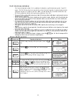
Page 54: ...redicted measurement when a bias of 0 is specified 0 60 specified level of bias Automatic halting mode measurement Bias 0 90 16 40 Automatic halting mode value 15 50 Predicted measurement when bias is 0 Note that the specified bias 0 60 does not affect the bias displayed here Without changing any of the specified in step 1 repeat steps 2 through 4 to measure again 5 times or more and obtain a comp...

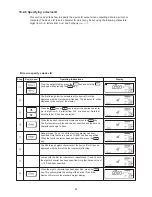
Page 55: ...used in comparative measuring mode subsections 12 2 1 and 12 2 2 Example Predicted value convergence range 0 5 Drying temperature 120 C Use the bias calculated following the procedures described in 12 2 1 and 12 2 2 to specify the bias shown here as 0 60 Also see 9 2 4 Bias on p 35 Place the sample onto the sample dish and begin measurement In the example shown here the initial weight is 10 213 gr...

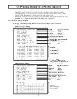
Page 56: ...pplier KETT ELECTRIC LABORATORY Model FD 720 Serial number AC00001 Device ID ABCD 123 Time of measurement 2003 08 08 Measuring conditions storage area 0 Measurement standard Wet base Measurement mode Automatic halting mode Drying temperature 110 C Automatic halting conditions 0 05 Bias 0 00 Sample code Time of measurement Pre drying weight g Post drying weight g Measured value Signature Pressing t...

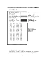
Page 57: ...consist of averages from 7 measurements taken over each 30 second interval for each set of weight data output Supplier KETT ELECTRIC LABORATORY Model FD 720 Serial number AC00001 Device ID ABCD 123 Sample code C 01 Date time of measurement 2003 08 08 15 24 Measuring conditions storage area 0 Measurement standard Dry base Measurement mode Automatic measuring mode Drying temperature 110 C Automatic ...

Page 58: ...5 07 Measuring conditions storage area 0 Measurement standard Dry base Measurement mode Comparative measuring mode Drying temperature 110 C Automatic halting conditions 0 05 Predicted value convergence range 0 5 Bias 0 00 Pre drying weight 5 6892g Elapsed measuring time Changes in drying temperature Measured value Predicted measurement Post drying weight 4 8637g ...

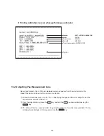
Page 59: ... set the output format to either TBL or PC 2 From the weight display press the key and hold the key down while pressing the key 3 The data will then be output in order beginning from the most recently measured data To stop printing while printing is still in progress press the key Printing calibration records when performing a calibration Supplier KETT ELECTRIC LABORATORY Model FD 720 Serial numbe...

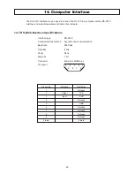
Page 60: ...1 RS 232C Interface Specifications Interface type RS 232C Communications method Asynchronous communication Baud rate 2400 bps Data bits 8 bits Parity None Stop bits 1 bit Connector Female D SUB9 pins Pin layout 5 4 3 2 1 9 8 7 6 Pin number Direction Description 1 Not used 2 Output TXD 3 Input RXD 4 Not used 5 GND 6 Not used 7 Not used 8 Not used 9 Not used Frame Shield ...

Page 61: ...llation of Main Unit on p 14 for instructions 14 2 2 FD 720 settings Turn on the power to the FD 720 and set the measurement data output destination to PC See 10 2 2 Specifying the type and format of output on p 38 for instructions 14 2 3 Starting up the computer Turn on the power to the computer and when Windows has started start the Data Logger soft ware KDL 01 or whatever software is to be used...

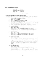
Page 62: ...top Cond _ _ X XX 4 byte automatic halting conditions setting delimiter 8 2 Timed halting format _Mode_ _Time delimiter _Setting_Temp _ _ XXX 3 byte temperature setting C delimiter _Drying_Time_ _ XXX 3 byte drying time setting min delimiter 8 3 High speed drying format _Mode_ _Rapid delimiter _Setting_Temp _ _ XXX 3 byte temperature setting C delimiter Automatic halting _Auto Stop Cond _ _ X XX 4...

Page 63: ... _ X X Predicted value convergence range delimiter 9 _Bias_ _ X XX delimiter Measurement output format tab Time min tab Temp C tab Mass g tab Moist delimiter Intermediate measurement output format tab XXX X 5 byte measuring time tab XXX 3 byte of thermistor temperature tab XXX XXXX 8 byte sample weight tab Moisture content XXX XX 6 byte moisture content delimiter Final measurement output format ta...

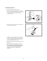
Page 64: ...rt or soiling difficult to remove If you find it particularly difficult to remove dirt or soiling wet a cloth in water or in water with a small amount of neutral detergent wring the cloth thoroughly and wipe Next rinse the cloth in water and wring it out to remove any detergent and wipe again then allow to dry 5 Maintenance of parts and accessories Remove the spoon spatula sample dish and wind shi...

Page 65: ...d check to see if any are burned out 4 If there are no burned out fuses return the fuse holder to its original position If there is a burned out fuse replace it with one of the spare fuses or with a compatible T8A 250V fuse 5 Return the fuse holder to its original position in the main unit 6 Insert the power cord back into the main unit If a fuse blows out again after being replaced then there may...

Page 66: ......

Page 67: ......

Page 68: ...0706 PA 0201 200 ...

Reviews: