

Assembly
19
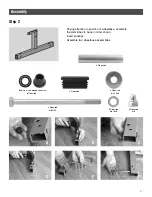
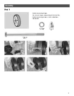
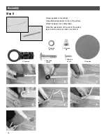
A
B
C
D
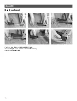
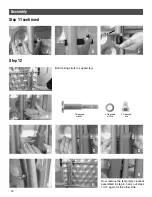
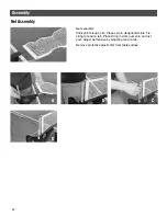
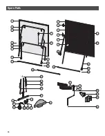
To properly open table into playing position: lock wheels (H), push the
thumb latch down on the left locking strut. Squeeze the strut on the right
side and lower table into playing position. Support the table as you
lower it; never allow it to drop down.
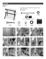
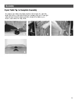
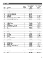
Open Table Top to Complete Assembly


