background image

4

US


Read all instructions before using or installing this product.


Button functions
Button

Function
Light on/o


•  Pressing the button switches the mirror on 

with the selected settings. The white LED 
goes o

 .

•  Pressing the button again switches the mirror 

o

 . The white LED lights up.

•  The white LED can be deactivated.


– Switch on the mirror.


– Press and hold the button for 15 seconds.


- The lighting gets lighter or darker.


- The lighting switches o

  brie

fl

 y and the 

white LED is deactivated.

To switch the white LED back on, repeat the 
described procedure.

Dimming the front, wall and washbasin 

lighting

•  Press the button when the light mirror is 

switched on and hold until the desired bright-

ness or the end value has been reached.

The setting is stored and reproduced when 

switched on again.

Setting the light colour cooler

•  Press and hold daylight white button and the 

light colour fades to cool white.

•  Release when the desired light colour has 

been reached.

The setting is stored and reproduced when 
switched on again.

Adjusting light colour - daylight white (cool 
white)

•  Press button and the colour temperature sets 

to 6500 Kelvin.

Setting the light colour warmer

•  Press and hold warm white button and the 

light colour fades to warm white.

•  Release when the desired light colour has 

been reached. 

The setting is stored and reproduced when 
switched on again.

Adjusting light colour - warm white

•  Press button and the colour temperature sets 

to 2700 Kelvin.

Heating on/o


•  Press button and the red LED lights up.
•  Pressing the button again switches the heat-

ing o

 , and the red LED goes out.

The heating switches o

  automatically after 

20 minutes.

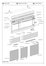
Replacement parts with order numbers

, see page 19.

The light sources may only be replaced by the 
manufacturer, its customer service or by an 
equally quali

fi

 ed person.

For information about warranty and mainte-
nance, see the enclosed 

Care Instructions 

and Warranty Card

.

Disposal instructions

This category of device does not belong in 
the domestic waste, but must be disposed of 
separately in accordance with the relevant 
local national regulations.

Summary of Contents for Edition 400 21553 171351

Page 1: ...US ES Instruction for use Manual de instrucciones de uso CA Instructions d utilisation Edition 400 311871_001 06 2020 21553 171351 ...

Page 2: ...a Prop 65 This product can expose you to chemicals inclu ding Di 2 ethylhexyl phthalate DEHP which is known to the State of California to cause cancer For more information go to www P65Warnings ca gov SAVE THESE INSTRUCTIONS This product must be installed by a qualified installer in accordance with local codes and regulations and according to the instructions for use in the enclosed manual Correct...

Page 3: ...nal light switch B installation type I or III refer to figure 3 on page 12 Depending on the type of connection the sockets are permanently supplied with voltage I or II or switch controlled III KEUCO recommends connection type I in combination with a switch for switching on off Before installation check whether the fastening materials included are suitable for the anchoring base The fas tening mate...

Page 4: ... been reached The setting is stored and reproduced when switched on again Adjusting light colour daylight white cool white Press button and the colour temperature sets to 6500 Kelvin Setting the light colour warmer Press and hold warm white button and the light colour fades to warm white Release when the desired light colour has been reached The setting is stored and reproduced when switched on ag...

Page 5: ...ponerte a productos quími cos como el Di 2 ethylhexyl phthalate DEHP que es conocidos por el Estado de California causar cáncer Para más información ve a www P65War nings ca gov GUARDE ESTAS INSTRUCCIO NES Este producto debe ser instalado por un técnico cualificado de acuerdo con los códigos y regula ciones locales y conforme a las instrucciones de uso en el manual adjunto La instalación correcta ...

Page 6: ...e imagen 3 en la página 12 Dependiendo del tipo de conexión los enchufes se alimentan permanentemente con voltaje I o II o conmutados III KEUCO recomienda la conexión tipo I en combinación con un interruptor de encendido y apagado Antes de la instalación compruebe si los materiales de fijación incluidos son adecuados para la base de anclaje Los materiales de fijación son adecuados exclusivamen te ...

Page 7: ...ma conexión Ajustar el color de luz blanco luz diurna blanco frío Pulse la tecla la temperatura de la luz se ajusta a 6500 Kelvin Ajustar el color de luz más cálido Pulse y mantenga pulsada la tecla de luz blanca cálida el color de luz pasa a blanco cálido Suelte la tecla al alcanzar el color de luz deseado El ajuste se guarda y se ajusta en la próxima conexión Ajustar el color de luz blanco cálid...

Page 8: ...la charge maximum prévue pour cette surface en livres kilogrammes CONSERVER LES PRÉSENTES INSTRUCTIONS Ce produit doit être monté par un installateur qualifié en conformité avec les codes et régle mentations locaux ainsi que les instructions d utilisation données dans le manuel joint Un montage correct réduit le risque d incen die de chocs électriques de brûlures et de blessures Consulter un élect...

Page 9: ...u avec un interrupteur d éclairage externe B mode de raccordement I ou III voir figure 3 à la page 12 En fonction du mode de raccordement les prises de courant sont en permanence alimentées en tension I ou II ou commutées III KEUCO conseille le mode de raccordement I en combinaison avec un bouton de marcher arrêt Avant de procéder à l installation vérifier que les ma tériels de fixation joints con...

Page 10: ...tré et il sera le même lors de la prochaine mise en marche Réglage de la couleur de la lumière blanc lumière du jour blanc froid Appuyer sur la touche la température de couleur se règle sur 6 500 Kelvin Réglage d une couleur de la lumière plus chaude Appuyer sur la touche blanc chaud et maintenir l appui la couleur de la lumière se superpose au blanc chaud Relâcher la touche lorsque la couleur de ...

Page 11: ...11 US Mounting dimensions ES Las dimensiones de montaje CA Dimensions de montage inch an mm pulgades y mm pouces et mm 6 9 16 167 55 1 2 1409 4 21 5 8 102 550 4 51 9 16 102 1310 25 9 16 650 21553 171351 ...

Page 12: ...12 Ø1 4 2 3 4 2 3 4 70 Ø6 70 2 3 4 70 2 3 4 70 74 13 16 76 3 4 1900 1950 23 9 16 598 13 16 20 44 7 16 1129 1 2 1 a 2 1 b 25 25 L1 N PE L N PE L N PE L1 3 I II III ...

Page 13: ...13 4 0 4mm 1 2 3 5 4mm 6 0 7 3 2 1 ...

Page 14: ...14 8 1 2 3 9 1 2 3 ...

Page 15: ...15 10 1 2 3 ...

Page 16: ...16 ...

Page 17: ...17 ...

Page 18: ...Liste de pièces 18 ...

Page 19: ...000 90107000011 90112170012 90105000055 90105000056 90106000008 90105000057 90101010059 90101010056 90101370053 90110000010 90109010001 90110000029 90107000005 90105000058 90105000059 90110000034 90110000033 90110000032 90110000010 90101010057 90108000012 90108000001 90108000014 21553 171351 ...

Page 20: ...hone 44 10442865220 E Mail admin keuco co uk FR KEUCO SARL 5 Rue du Martelberg F 67700 Monswiller Téléphone 33 3 88700200 E Mail bureau keuco fr NL KEUCO GmbH Co KG Kantoor Nederland Postbus 1286 5004 BG Tilburg Telefoon 31 88 6 333 999 E Mail info keuco nl RU KEUCO GmbH Co KG Представительство в России Космодамианская набережная дом 4 22 корпус Б 115035 Москва Электронная почта US VELLA LLC d b a...

Reviews: