background image


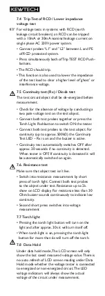
7.4  Trip Test of RCD / Lower impedance  


voltage test


For voltage tests in systems with RCD (earth  
leakage circuit breakers) an RCD can be tripped 
with a 10mA or 30mA nominal leakage current on 
single phase AC 230V power system.


•  Connect probes “L1” and ”L2” between L and PE 

of RCD protected system.


•  Press simultaneously both of Trip TEST RCD Push-

buttons.


• The RCD should trip.


• This function is also used to lower the impedance  

of the test load to clear a higher level of 'ghost' or  
interference voltage.


7.5 Continuity test (Rx) / Diode test


 The test circuit/object shall be de-energized before 
measurement. 


•  Check for the absence of voltage by conducting a 

two pole voltage test on the test object.


•  Connect both test probes together or press the 

Torch Light Pushbutton to switch ON the tester.


•  Connect both test probes to the test object. For 

continuity (up to approx. 500k�) the Continuity 
Test LED – Rx is on and the buzzer is active.


•  Continuity test automatically switches OFF after 

approx. 30 seconds if no continuity is detected. 
When tester is OFF, If continuity is detected it will 
be automatically switched on again.


7.6. Resistance test


Make sure that object test isn’t live. 


•  Switch into resistance measurement by short 

press of torch light. Connect both test probes 
to the object under test. Resistance up to 2k 
show on LCD display. For resistance less than 30 
Ohm buzzer sounds continuously to indicate low 
continuity.


•  Second short press switches into voltage 

measurement


7.7 Torch light


•  Pressing the torch light button will turn on the 

light and after approx. 30s it will turn itself off. 


•  When torch light is on, pressing the torch light 

button for more than 6s will turn off the torch.


7.8  Data Hold 


 Under data hold mode, The LCD screen will only 
show the last saved measured voltage value. There is 
no auto refresh of LCD screen reading under Data 
Hold mode whether the voltage tester is connected 
to energized or non-energized circuit. The LED 
voltage indicators will always show the actual 
voltage of the circuit under measurement.

Summary of Contents for KT1795

Page 1: ...KT1795 Current Voltage Tester Instruction Manual...

Page 2: ...ts 7 1Voltage Test 7 2 Single pole phase test 7 3 Phase Rotation Test 7 4 Trip Test of RCD Lower ImpedanceVoltage test 7 5 Continuity test Rx Diode test 7 6 Resistance test 7 7 Torch Light 7 8 Data Ho...

Page 3: ...instruction manual and comply with it in all sections Failure to read the tester manual or to comply with the warnings and references contained herein may result in serious bodily injury or tester dam...

Page 4: ...voltage source such as the KEWPROVE3 opening unit Make sure that the cables tested for current are double insulated The tester must no longer be used if one or more functions fail or if no functional...

Page 5: ...only be performed on double insulated cables If the indication voltage present appears although the checked part is considered as disconnected it is recom mended to verify additional measures if the m...

Page 6: ...t It can be switched on with the torch light button 6 2 Auto power off Tester is automatically powered off after 30 sec when there is no signal contacted to the probes The torch light switches off aft...

Page 7: ...ment under test aren t good enough Verification of live circuit shouldn t be dependent on this Single pole phase test only but on the voltage test Hold the tester well in your hand Connect the L2 prob...

Page 8: ...active Continuity test automatically switches OFF after approx 30 seconds if no continuity is detected When tester is OFF If continuity is detected it will be automatically switched on again 7 6 Resis...

Page 9: ...the battery door and replace the batteries Insert new batteries according to the engraving on the battery door Re assemble battery door Confirm that the battery door case is properly locked prior to m...

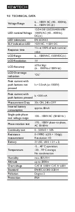
Page 10: ...s not pressed Is 3 5mA at 1000V Peak current with push buttons pressed Is 300 mA Measurement Duty 30s ON 240s OFF Internal battery consumption approx 80mA Single pole phase test voltage range 100 1000...

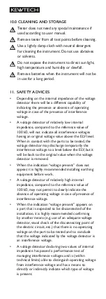
Page 11: ...o a level below the ELV but it will be back to the original value when the voltage detector is removed When the indication voltage present does not appear it is highly recommended installing earthing...

Page 12: ...It covers all manufacturing defects for a two year period but Kewtech reserves the right to exclude abuse or accidental damage RE CALIBRATION SERVICE Regular re calibration is recommended for this ins...

Reviews: