background image

KEWTECH

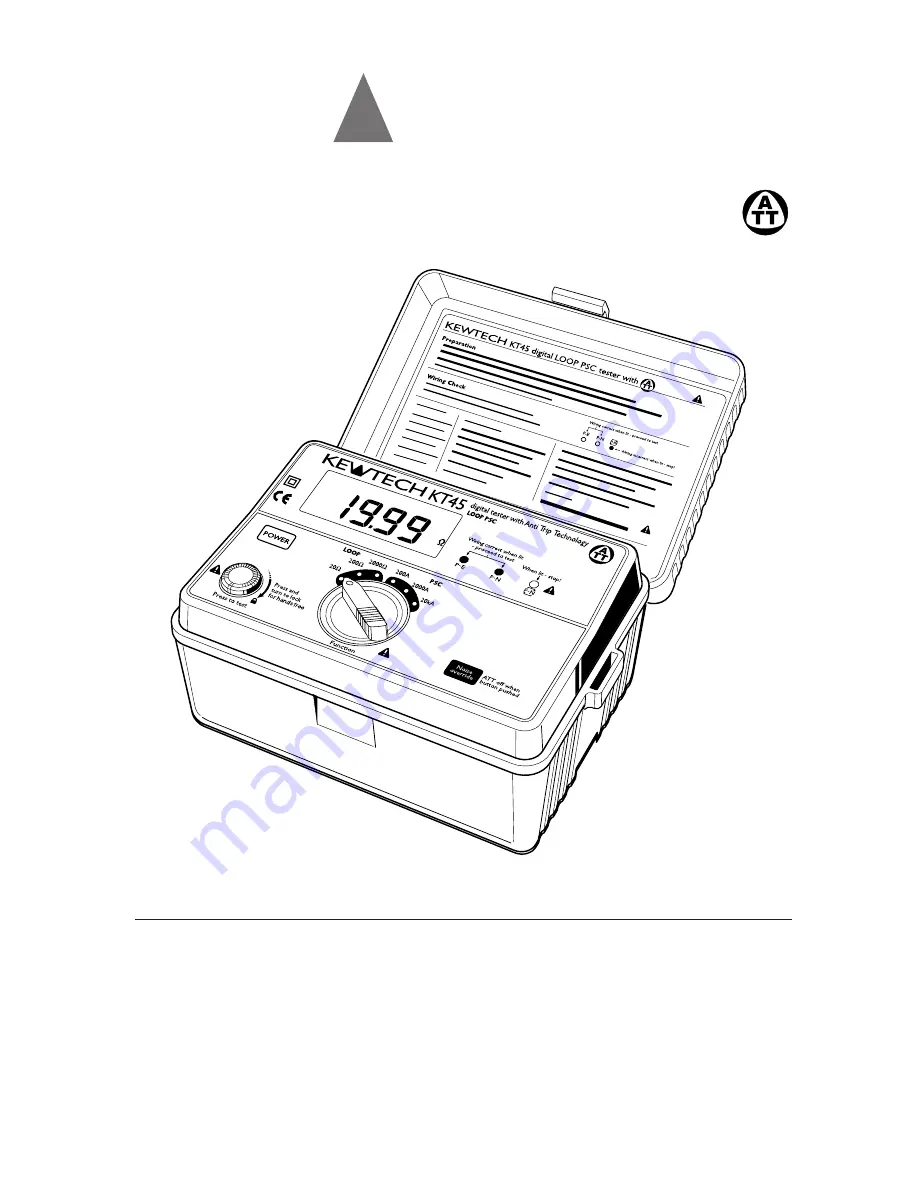
KT45

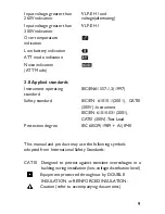
digital LOOP PSC tester with

Instruction manual

Summary of Contents for KT45

Page 1: ...KEWTECH KT45 digital LOOP PSC tester with Instruction manual ...

Page 2: ... saves time and money by not having to take the RCD out of circuit during testing and is a safer procedure to follow With the ATT function a test current of 15mA or less is applied between line earth It enables LOOP measurement without tripping most RCDs If there is doubt as to whether this tester will by pass a particular RCD contact Kewtech with details of manufacturer model no rating and sensit...

Page 3: ...tal work This is because the earth has a current flowing through it for the duration of the test 1 4 Never open the instrument case except for battery replacement and in this case disconnect all leads first there are dangerous voltages present Only trained competent Electronic engineers should open the case Send the unit to Kewtech if a fault develops 1 5 This instrument is primarily protected by ...

Page 4: ...ce worn and or damaged leads with new ones approved by Kewtech immediately Only use accessories recommended by Kewtech as they are designed to work with the tester The use of any other items is prohibited as they may not have the same safety features built in and may degrade performance 1 13 Users of this equipment and or their employers are reminded that Health and Safety Legislation require them...

Page 5: ...er Switch 3 Test Button 4 Function Range Switch 5 Wiring Check LEDs LED indication of correct polarity is that the P E and P N LEDs are lit P and N are reversed when the reverse LED is lit 6 Noise override Switch LCD display 5 6 4 1 2 3 Fig 1 Fig 2 ...

Page 6: ...UK mains test lead with IEC Connector ACC016E Distribution board fused test lead Fuse 10A 600V fast acting ceramic Test lead carry pouch for hands free for hands free Black neutral Red KAMP11UK ACC016E phase Green earth Fig 3 ...

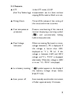
Page 7: ...utomatically halting further measurements Main Voltage When connecting Test Lead to circuit Indication voltage between L PE is displayed If the voltage is lower than 100V displayed as V L PE Lo If the voltage is between 260V and 300V voltage and V L PE Hi is displayed alternately When the voltage is 300V or more V L PE Hi is displayed Low battery warning symbol appears in the display if the batter...

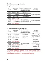
Page 8: ... 199 9Ω 2 3A 20ms 3 rdg 4dgt 2000Ω 0 1999Ω 15mA 360ms 20Ω 0 00 19 99Ω ATT 1 L N 20Ω P N 25A 30ms 3 rdg 6dgt 200Ω 0 0 199 9Ω N E 11mA approx 2s ATT 1 L N 20Ω Measuring Nominal test current at Intrinsic Range range 0Ω external loop accuracy Magnitude Duration 200A 0 0 199 9A 2 3A 20ms 2000A 0 1999A 25A 10ms 20kA 0 00 1 99kA 25A 10ms 200A 0 0 199 9A ATT 1 L N 20Ω 2000A 0 0 1999A P N 25A 30ms ATT 1 L ...

Page 9: ...ltage 2 The voltage and V L PE Hi is displayed on the LCD alternately when the voltage is 260V or more and under 300V 2 5 Reference conditions Ambient temperature 23 5 Relative humidity 60 15 Nominal system voltage 230V 50Hz and frequency Altitude Less than 2000m ...

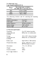
Page 10: ... less no condensation humidity Battery type Eight AA R6 or LR6 batteries Measurement times approx 1500 times or more ATT 500 times or more Dimensions 175 x 115 x 85 7mm Weight 810g Maximum altitude 2000m Over range indication OL 8 Range Operating range compliant with EN61557 3 operating error 20Ω 0 35 to 19 99Ω 200Ω 20 0 to 199 9Ω 2000Ω 200 to 1999Ω Ambient temperature 0 and 35 Phase angle 0 to 18...

Page 11: ... standard Safety standard IEC EN 61010 1 2001 CATIII 300V Instrument IEC EN 61010 031 2001 CATIII 300V Test Lead Protection degree IEC 60529 1989 A1 IP40 This manual and product may use the following symbols adopted from International Safety Standards CAT III Designed to protect against transient overvoltages in a building wiring installation low voltage distribution level Equipment protected thro...

Page 12: ...xceed that specified or appropriate for the over current protective device installed in the circuit KT45 takes a current from the supply and measures the difference between the unloaded and loaded supply voltages From this difference it is possible to calculate the loop resistance For a TT system the earth fault loop impedance is the sum of the following impedances Impedance of the power transform...

Page 13: ... shows in marked line the Fault loop impedance for TN system In accordance with the international standard IEC 60364 for a TT system the following condition shall be fulfilled for each circuit RA must be _ 50 Ia where RA is the sum of the resistances of the local earth system R and the protective conductor connecting it to the exposed conductor part 50V is the maximum voltage limit it may be 25V i...

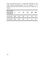
Page 14: ...s the rated residual operating current IΔn For example in a TT system protected by an RCD the maximum RA values are as follows Rated residual operating cur 10 30 100 300 500 1000 rent I n mA Ra at 50V Ω 5000 1667 500 167 100 50 Ra at 25V Ω 2500 833 250 83 50 25 ...

Page 15: ...nce with the international standard IEC60364 for a TN system The following condition shall be fulfilled for each circuit Zs _ Uo Ia where Zs is the earth fault loop impedance voltage is the nominal voltage between phase and earth and Ia is the current that causes the automatic disconnection of the protective device within the time stated in the following table Uo Volts T seconds 120 0 8 230 0 4 40...

Page 16: ... could be If the prospective fault current is measured its value must be higher than the Ia value of the protective device concerned Rating Disconnecting Time 5s Disconnecting Time 0 4s A Ia A Zs Ω Ia A Zs Ω 6 28 8 20 47 4 90 10 46 5 00 82 2 80 16 65 3 60 110 2 10 20 85 2 70 147 1 56 25 110 2 10 183 1 25 32 150 1 53 275 0 83 40 190 1 21 320 0 72 50 250 0 92 470 0 49 63 320 0 71 550 0 42 80 425 0 5...

Page 17: ...phase and neutral The protective short circuit or fault current at any point within an electrical installation is the current that would flow in the circuit if no circuit protection operated and a complete very low impedance short circuit occurred The value of this fault current is determined by the supply voltage and the impedance of the path taken by the fault current Measurement of prospective ...

Page 18: ...ent without tripping the RCDs with the rated residual current of 30mA or more Measurement in ATT mode requires longer time than that is required for the other measurements approx 10 sec When measuring a circuit with a large electrical noise the NOISE mark is displayed on the LCD and the measurement time will be extended to 20 sec When the noise is so great as to influence the test result the NOISE...

Page 19: ... NOT displayed or the RED LED is on for any reason DO NOT PROCEED AS THERE IS INCORRECT WIRING The cause of the fault must be investigated and rectified 4 1 3 Voltage Measurement When the instrument is first connected to the system it will display the phase earth voltage which is updated every 1s This mode is cancelled the first time the test button is pressed If this voltage is not normal or as e...

Page 20: ...witch up a range to the 200Ω range b Loop impedance at the distribution board Warning Although it is fully protected no bangs never connect phase to phase 400VAC to this instrument Select the 20Ω 200Ω or 2000Ω range as required Connect the distribution board lead model ACC016E to the IEC socket on the instrument Connect the green crocodile clip of the ACC016E to the earth the black neutral lead to...

Page 21: ...cept the earth clip should be connected to the neutral of the system i e the same point as the black neutral probe If the system has no neutral then you must connect the black neutral probe to the earth i e same point as the green earth clip This will only work if there is no RCD in this type of system 4 3 Measurement of PSC Prospective Short Circuit Current Warning Although it is fully protected ...

Page 22: ...ad first Note PSC function has a power factor correction of 0 84 Voltage V PSC x 0 84 LOOP Ω If the PSC ranges are selected whilst connected to a socket outlet via the mains lead KAMP11UK a test will take place between Phase and Earth due to the fixed wiring of the mould ed mains plug i e a Phase Earth fault current test When measuring the Phase Earth fault current with the ATT mode activated RCD ...

Page 23: ...ts are conducted by simply disconnecting and reconnecting the red phase prod of the ACC016E avoiding the need to physically press the test button i e hands free 5 3 When the display shows the low battery indication disconnect the test leads from the instrument Remove the battery cover and the batteries 5 4 If at any time during testing there is a momentary degradation of reading this may be due to...

Page 24: ...t To avoid possible electrical shock disconnect the test probe before opening the cover for battery replacement CAUTION Install batteries in correct polarity as marked inside 1 Disconnect Test Lead from the instrument 2 Open the battery compartment cover by unscrewing the metal captive screw to reveal battery compartment Always replace all eight batteries with new ones at the same time Battery typ...

Page 25: ...P11UK for testing at sockets is part of the instrument It directly affects the accuracy of the loop and PSC readings As such always keep it with the instrument and remember to return it with the instrument when servicing and calibration is required In a similar way the ACC016E is part of the instrument The ACC016E leads are fused and fuses are rated at 10A 600V high rupture ceramic types If they s...

Page 26: ...st lead pouch in the following sequence 1 Pass the strap down through the first lug under the case and up through the other lug 2 Slide the shoulder pad onto the strap 3 Feed the strap down through the slots in the back of the test lead pouch 4 Pass the strap through the buckle adjust the strap for length and secure ...

Page 27: ...KEWTECH Kewtech Corporation Limited St Catherine s Grove Lincoln LN5 8NA www kewtechcorp com Distributor 92 1650 05 02 ...

Reviews: