background image

4

EN

2 - INTRODUCING THE PRODUCT

3 - PRELIMINARY CHECKS

Before installing the product, perform the following checks and in-

spections:

check that the barrier is suitable for automation;

the weight and size of the barrier must be within the operating limits 

specified for the automation system in which the product is installed;

check that the barrier has firm, effective mechanical safety stops;

make sure that the product fixing zone is not subject to flooding;

high acidity or salinity or nearby heat sources might cause the pro-

duct to malfunction;

in case of extreme weather conditions (e.g. snow, ice, wide tempe-

rature variations or high temperatures), friction may increase, cau

-

sing a corresponding rise in the force needed to operate the system; 

the starting torque may therefore exceed that required in normal 

conditions;

check that when operated by hand the barrier moves smoothly wi-

thout any areas of greater friction or derailment risk;

check that the barrier is well balanced and will therefore remain sta-

tionery when released in any position;

check that the electricity supply line to which the product is to be 

connected is suitably earthed and protected by an overload and dif-

ferential safety breaker device;

the system power supply line must include a circuit breaker device 

with a contact gap allowing complete disconnection in the condi-

tions specified by class III overvoltage;

ensure that all the material used for installation complies with the 

relevant regulatory standards.

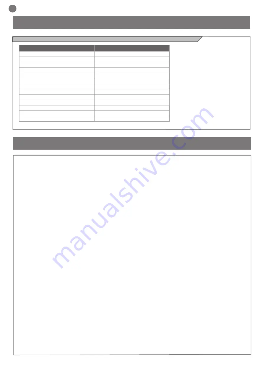
2.1 - Technical characteristics

TECHNICAL SPECIFICATIONS

900ALT624K

Torque

250 Nm

Temporary service

80 %

Opening time

6/*12 sec

Control unit

CT10224

Power supply

Vac (Vdc) 230 (24)

Motor absorption

1,3 A

Input power

300 W

Integrated lights

yes

Protection class

IP 54

Dimensions (L-P-H)

450-280-1188 mm

Weight

67 Kg

Operating temperature

-20 °C + 55 °C

Maximum length of bar

6*(8 mt)

* with 8 m bar

Summary of Contents for 900ALT624K

Page 1: ...Automation for rod barriers up to 6 m ALT6K Instructions and warnings for installation and use Management System ISO 9001 2008 www tuv com ID 9105043769...

Page 2: ...alling the Product Installing Release Adjustment of rod angle Inversion of direction of opening Balancing Testing and commissioning Testing Commissioning Instructions and warnings for the final user E...

Page 3: ...er cable is damaged it must be replaced by the manufac turer or its after sales service or in all cases by a person with similar qualifications to prevent all risks do not allow parts of the automatio...

Page 4: ...operated by hand the barrier moves smoothly wi thout any areas of greater friction or derailment risk check that the barrier is well balanced and will therefore remain sta tionery when released in any...

Page 5: ...n the locking nut on the rocker arm for ALT6 emergency manoeuvre Perform the manual manoeuvre To engage the transmission again turn the allen wrench back to its original position Fig 8 2 and close the...

Page 6: ...f the dangers and risks still present 5 1 Testing All system components must be tested following the procedures outlined in the respective instruction manuals Check that they meet the guidelines in Ch...

Page 7: ...l non automated opening device To do this you must run the manual release Release and manual movement before performing this operation pay attention that the device can be released only when the door...

Page 8: ...nsions Main components IMAGES MAIN COMPONENTS 1 SPRING SHORT TIE ROD VERTICAL POSITION 2 SPRING LONG TIE ROD DIAGONAL POSITION 3 MOTOR 24 Vdc 4 MECHANICAL STOP ADJUSTING 5 UNLOCK KEY 6 CONTROL BOARD 3...

Page 9: ...9 Fig 2 Typical Installation Fig 4 Fixing the barrier body Fig 3 Preparation of the base...

Page 10: ...10 Fig 6 Adjustment of bar angle ALUMINUM TUBOLAR BAR Fig 5 Fixing round bar square bar Fig 7 Inversion of direction of opening and balancing...

Page 11: ...11 1 2 3 WARNING WHEN UNLOCKING THE BAR THE BAR CAN FALL OR RAISE DO NOT STAND BELOW THE BAR Fig 8 Release system...

Page 12: ...N 2501 3000 4D2 3001 3500 3D1 3501 4000 3D1 4001 4500 3D1 4501 5000 5001 5500 5501 6000 BAR RUBBER FENCE 2x L BAR LENGHT mm POSITION 3501 4000 3D1 4001 4500 3D1 4501 5000 5001 5500 5501 6000 L BAR LEN...

Page 13: ...9000 BAR FENCE 2x MOBILE STAND L BAR LENGHT mm POSITION 3501 4000 3D1 4001 4500 2D1 4501 5000 5001 5500 5501 6000 BAR FENCE 1x MOBILE STAND L BAR LENGHT mm POSITION 2501 3000 4D2 3001 3500 3D1 3501 4...

Page 14: ...14 NOTES...

Page 15: ...ery Directive 2006 42 EC Direttiva bassa tensione Low voltage Directive 2006 95 EC Direttiva compatibilit elettromagnetica EMC Directive 2004 108 EC Direttiva R TTE R TTE Directive 1999 5 EC Secondo q...

Page 16: ...Key Automation S r l Via A Volta 30 30020 Noventa di Piave VE T 39 0421 307 456 F 39 0421 656 98 info keyautomation it www keyautomation it Instruction version 580ISALT REV 02...

Reviews: