WIND LIGHT
WIND
22
EN
TECHNICAL DATA
WIND LIGHT
WIND
Power supply
230 Vac (+/- 10%) 50/60 Hz
230 Vac (+/- 10%) 50/60 Hz
Max. drawdown
80 W
150 W
Electric lock voltage
12 Vdc
12 Vdc
Battery charger
Charging voltage 27.5 Vdc I max = 200 mA with
control unit powered up
Charging voltage 27.5 Vdc I max = 200 mA with
control unit powered up
Electric motor
24 Vdc max power 80 VA
24 Vdc max power 80 VA
Recommended max. weight for
door leaf
1 leaf 120 Kg; 2 leaves 80 Kg + 80 Kg
1 leaf 160 Kg; 2 leaves 130 Kg + 130 Kg
Opening speed
Adjustable max 70 cm/s (per leaf)
Adjustable max 70 cm/s (per leaf)
Closing speed
Adjustable max 60 cm/s (per leaf)
Adjustable max 60 cm/s (per leaf)
Opening pause time
Adjustable from 0 to 60 seconds
Adjustable from 0 to 60 seconds
Operating temperature
from -20°C to +55°C
from -20°C to +55°C
Protection class
IP 22
IP 22
Crosspiece length
max 7000 mm
max 7000 mm
2.3 - Technical specifications
3 - PRELIMINARY CHECKS
Before installing the product, perform the following checks and in-
spections:
Make sure that the door is suitable for automation;
the weight and size of the door must be within the operating limits
specified for the automation system in which the product is installed;
check that the door has firm, effective mechanical safety stops;
make sure that the product fixing zone is not subject to flooding;
high acidity or salinity or nearby heat sources might cause the pro-
duct to malfunction;
in case of extreme weather conditions (e.g. snow, ice, wide tempera-
ture variations or high temperatures), friction may increase, causing a
corresponding rise in the force needed to operate the system; the star-
ting torque may therefore exceed that required in normal conditions;
check that when operated by hand the door moves smoothly without
any areas of greater friction or derailment risk;
check that the door is well balanced and will therefore remain statio-
nery when released in any position;
check that the electricity supply line to which the product is to be
connected is suitably earthed and protected by an overload and dif-
ferential safety breaker device;
the system power supply line must include a circuit breaker device
with a contact gap allowing complete disconnection in the condi-
tions specified by class III overvoltage;
ensure that all the material used for installation complies with the
relevant regulatory standards.
4.1 - Pre-installation setup
To ensure correct installation, the existing structures must first be
checked.
The crosspiece must be mounted on a flat surface solid enough to
support the weight of the leaves to be used. If the wall or support
to be used does not meet these requirements, a suitable tubular
steel structure will have to be pre-fitted, since the crosspiece is not
self-supporting.
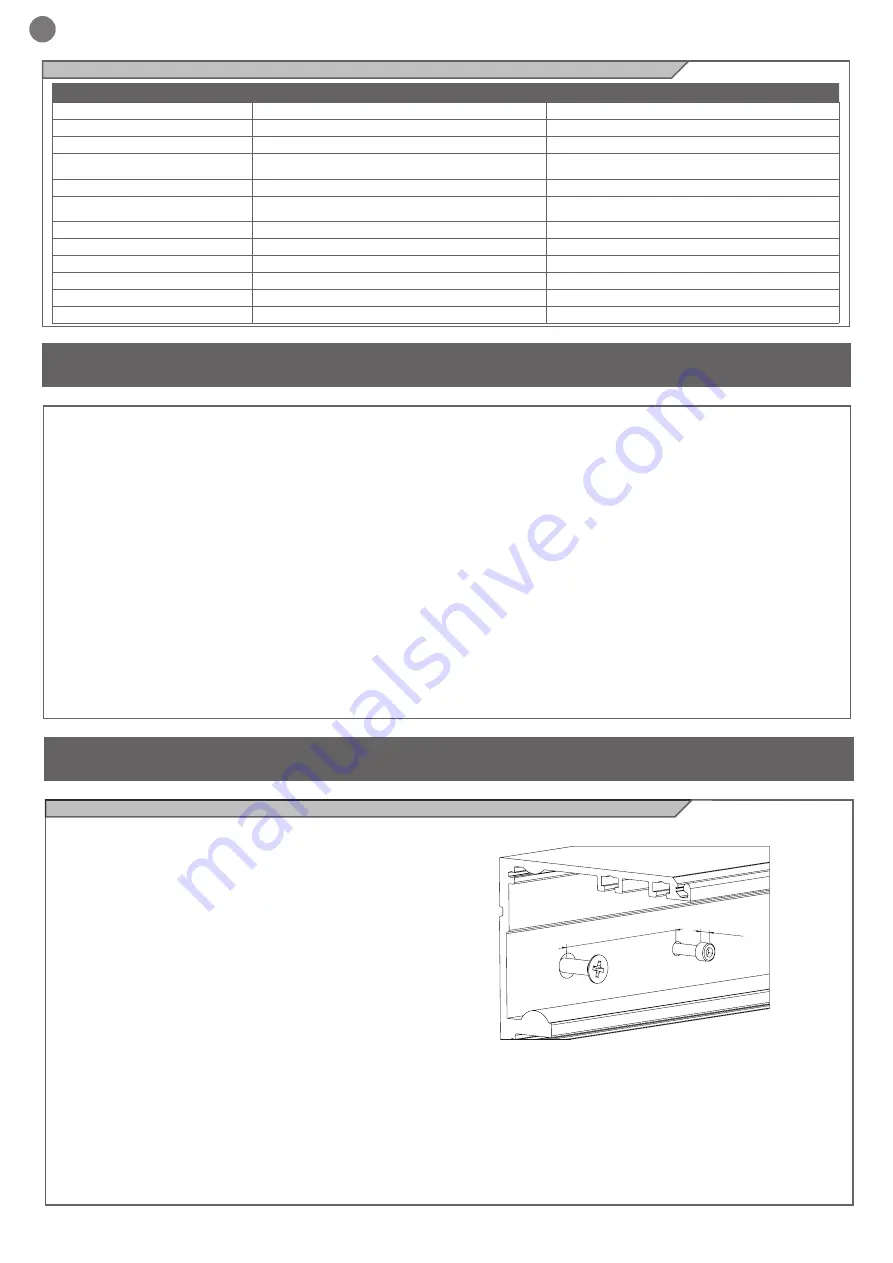
A spirit level should be used to ensure that the crosspiece is pro-
perly levelled. Fix the crosspiece to the wall or support using steel
plugs or equivalent fixtures shown in the table. Note that the head
of the fixing screw must not be more than 8 mm thick.
The distance between fixing points must not exceed 600 mm. Take
care not to damage the track during hole drilling and fixing proce
-
dures. Clean the track thoroughly after fixing to ensure trouble-free
operation of the automation.
Max 8
Max 600 mm
4 - INSTALLING THE PRODUCT
Summary of Contents for WIND
Page 17: ...IT 17 NOTE ...
Page 33: ...33 EN NOTES ...
Page 49: ...49 FR REMARQUES ...
Page 65: ...65 ES NOTAS ...


