NF4027P Facial recognition user manual V1.00
10
/
34
Chapter 2 Installation
2.1
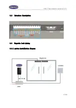
interface description
Screen
Swipe area
LED light
RGB Camera
Infrared Camera
infrared light
RESET
HDMI
SN
Bracket slot
Screw hole
USB
Heat sink
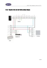
WD0
WD1
232 TXD 232 RXD
+12V
GND
RJ45-1 RJ45-2 RJ45-3 RJ45-6
GND
NC
NO
COM
COM PORT
WG_OUT
Lock
POWER
NETWORK
Positive and
negative power
supply. If they
are reversed,
the device will
not start. Power
adapter requires
12-16V, 2A
cable. From left to right
are:
TX+, orange white line
TX-, orange line
RX+, green white wire
RX-
, green line
Serial signal
output. serial
communication
TXD, RXD
Wiegand 26
signal output.
Wiegand
signal 0 output,
1 output
Relay switch
signal output.
From left to right:
NC, NO, COM.
Summary of Contents for NF4027P
Page 4: ...NF4027P Facial recognition user manual V1 00 4 34...
Page 9: ...NF4027P Facial recognition user manual V1 00 9 34 1 6 Dimensions...
Page 15: ...NF4027P Facial recognition user manual V1 00 15 34...
Page 28: ...NF4027P Facial recognition user manual V1 00 28 34 After the device goes online...
Page 31: ...NF4027P Facial recognition user manual V1 00 31 34 in Access Level tick the security groups...
Page 33: ...NF4027P Facial recognition user manual V1 00 33 34...


