background image

                                                                                        NF4027P Facial recognition user manual V1.00 


2

34


INDEX 


Chapter 1    introduction

 ........................................................................................................................... 5


1.1


Apparatus shape

 .................................................................................................................. 5


1.2


Model

 ........................................................................................................................................ 5


1.3


Application

 ........................................................................................................................... 5


1.4


Feature

 .................................................................................................................................... 5


1.5


Specification

 ...................................................................................................................... 6


1.6


Dimensions

 ............................................................................................................................. 9


Chapter 2    Installation

 ........................................................................................................................... 10


2.1


interface description

 .................................................................................................. 10


2.2


Installation steps

 ......................................................................................................... 11


Chapter 3    wiring

 ................................................................................................................................... 16


3.1


Material / Tool List

 .................................................................................................... 16


3.2


Interface description

 .................................................................................................. 17


3.3


Magnetic lock wiring

 .................................................................................................... 17


3.3.1


system installation diagram

......................................................................... 17


3.3.2


Magnetic lock and exit button wiring diagram

 .................................. 18


3.3.3


Magnetic Lock mechanical switch wiring diagram

 ............................. 19


3.4


Automatic induction door wiring

 ........................................................................... 20


3.4.1


Automatic induction door system installation diagram

 ................ 20


3.4.2


Automatic door sensor head switch wiring diagram

 ......................... 21


Summary of Contents for NF4027P

Page 1: ...User Manual Thank you for selecting our products Please read this manual before use NF4027P NexFace Facial Recognition KEYKING GROUP...

Page 2: ...0 2 2 Installation steps 11 Chapter 3 wiring 16 3 1 Material Tool List 16 3 2 Interface description 17 3 3 Magnetic lock wiring 17 3 3 1 system installation diagram 17 3 3 2 Magnetic lock and exit but...

Page 3: ...NF4027P Facial recognition user manual V1 00 3 34 3 5 Precautions 21 Chapter 4 System setting 25 4 1 NF4027P setting 25 4 2 Sphinx4 4 setting 25 Chapter 5 Registered 29 Chapter 6 Test 34...

Page 4: ...NF4027P Facial recognition user manual V1 00 4 34...

Page 5: ...for office areas hotels access gates office buildings schools shopping malls shops communities public services and management projects etc 1 4 Feature Support for external HDMI large screen only suppo...

Page 6: ...illion identification records including the latest 10 000 live capture photos When the face database is 3000 and the misrecognition rate is 3 10000 the 1 N recognition accuracy rate is 99 7 Fast recog...

Page 7: ...t Vertical wide angle Horizontal wide angle Core parameter CPU 4 cores 1 8 GHz storage Memory 2G storage 8G Accessories Fill light Infrared LED fill light Card reader module U card reader only support...

Page 8: ...ntification rate the recognition accuracy rate is 99 7 Stranger detection support Recognition distance configuration support UI interface configuration support Remote upgrade of equipment support Depl...

Page 9: ...NF4027P Facial recognition user manual V1 00 9 34 1 6 Dimensions...

Page 10: ...RJ45 1 RJ45 2 RJ45 3 RJ45 6 GND NC NO COM COM PORT WG_OUT Lock POWER NETWORK Positive and negative power supply If they are reversed the device will not start Power adapter requires 12 16V 2A cable Fr...

Page 11: ...wire using tools such as scissors to expose the wire as shown b Press the orange button at each connector on the green bar to insert the wire end into the hole then loosen the orange button to secure...

Page 12: ...vice on the wall you can directly refer to step 6 After the device is powered on start using the device 2 Place the hole paper on the wall keep the horizontal line parallel to the ground when pasting...

Page 13: ...g of the connected cable out of the outlet hole If you need to reset the cable and HDMI cable please pass it out from the outlet hole at this step 5 Move the bracket so that the three holes on the bra...

Page 14: ...ctor on the back of the device 7 Screw the countersunk screw into the bracket for two turns then align the slot under the device with the hook under the bracket Use a hexagon socket tool or a hex driv...

Page 15: ...NF4027P Facial recognition user manual V1 00 15 34...

Page 16: ...lectromagnetic lock optional 1 When the power is off the door is opened and when the power is turned on the door is locked 4 Access control power supply optional 1 Power supply to the electromagnetic...

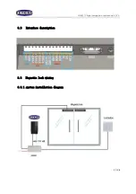
Page 17: ...NF4027P Facial recognition user manual V1 00 17 34 3 2 Interface description 3 3 Magnetic lock wiring 3 3 1 system installation diagram...

Page 18: ...NF4027P Facial recognition user manual V1 00 18 34 3 3 2 Magnetic lock and exit button wiring diagram...

Page 19: ...NF4027P Facial recognition user manual V1 00 19 34 3 3 3 Magnetic Lock mechanical switch wiring diagram...

Page 20: ...NF4027P Facial recognition user manual V1 00 20 34 3 4 Automatic induction door wiring 3 4 1 Automatic induction door system installation diagram...

Page 21: ...recognition user manual V1 00 21 34 3 4 2 Automatic door sensor head switch wiring diagram 3 5 Precautions 1 Touch the cable inside the Exit button panel as far as possible from the center of the bac...

Page 22: ...host does not use dedicated power extension cable and the distance is long it will result in excessive cable equivalent resistance which will be prone to abnormal phenomena such as insufficient termi...

Page 23: ...ower cable weak power part 40cm the power line strong power part The power cable weak power part must not be extended by more than 2 meters Otherwise the voltage at the host terminal of the device wil...

Page 24: ...be too thin such as a thin wire It is recommended to connect multiple strands of the same cable or use a thick copper core cable to ensure a voltage 11V note If the network cable is used the extensio...

Page 25: ...Facial recognition user manual V1 00 25 34 Chapter 4 System setting 4 1 NF4027P setting Set ip in NF4027p make sure it is in the same IP segment with sphinx 4 2 Sphinx4 4 setting Communication config...

Page 26: ...NF4027P Facial recognition user manual V1 00 26 34 Add face recognition device setup hardware face recognition...

Page 27: ...NF4027P Facial recognition user manual V1 00 27 34 As shown in the figure below click search fill the IP segment that covers the NF4027P...

Page 28: ...NF4027P Facial recognition user manual V1 00 28 34 After the device goes online...

Page 29: ...Facial recognition user manual V1 00 29 34 Chapter 5 Registered Click Add a Personnel to pop up the following window and click to add new one In Basic Information fill in the ID name department infor...

Page 30: ...ial recognition user manual V1 00 30 34 In Card tick the Use Access Card obtain the card number through the card issuer or card reader or manually enter the card number card number face recognition te...

Page 31: ...NF4027P Facial recognition user manual V1 00 31 34 in Access Level tick the security groups...

Page 32: ...NF4027P Facial recognition user manual V1 00 32 34 In Face Info check Use face recognition under NF1000 and check the face recognition device in the Device Name box...

Page 33: ...NF4027P Facial recognition user manual V1 00 33 34...

Page 34: ...ecognition user manual V1 00 34 34 Chapter 6 Test In Monitor choose Photo Viewer then Face Recognition Viewer we can see the registered face and the new coming face If the recognition is Successful th...

Reviews: