6
A
30
30
B
58
58
38
8
1
39
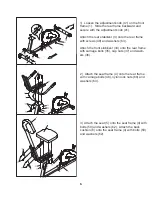
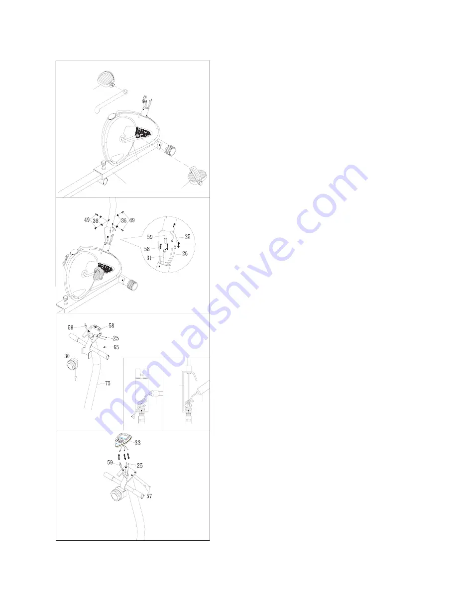
4) Thread the right pedal (39) onto the right side of
the crank (8) as shown. Tighten the pedal securely.
Select the right pedal strap which has “R” marked
on the bottom side of the strap. Snap the three hole
end onto the inside edge of the right pedal (39).
Snap the other three hole end onto the outside edge
of the right pedal (39). Select adjustment holes
which allow your foot to be easily removed from the
pedals. Repeat with the left pedal and strap.
5) Insert the sensor wire (packed with tension con-
troller) from the top of the handlebar post (75).
Connect the sensor wire to the one on the main
frame, and insert the sensor wire up into the handle-
bar post.
Fix the handlebar post (75) onto the main frame (1)
with screws (49) and arc washers (36).
6) Install the tension controller (30).
Step 1: Put the tension controller’s cable end into
the spring hook.
Step 2: Pull and force the cable into the gap of the
plate.
Step 3: Insert the tension controller into the “A”
hole of handlebar post and attach it with
the screw (65) attathed
7) Connect the sensor wire to the computer (33)
and fix it on the top of the handlebar post by the
screws (57) attached.

