4
Verification
40
Keysight 11713D/E Operating and Service Manual
Operator’s Check for Local Operation
Recommended test equipment
lists the test equipment required for performance test verification and equipment
troubleshooting. Equipment other than the recommended models can be used, provided minimum
specifications are satisfied.
Procedure
1
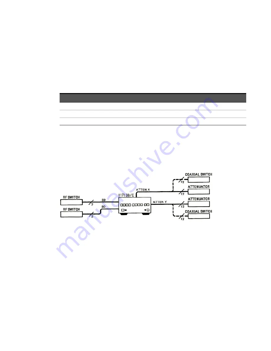
Configure the switching system as illustrated in
by following all steps described in
Figure 4-1
Switching system for verification
2
Once configuration is completed, press and depress the 10 numbered pushbuttons on the
driver front panel. Each LED should alternate between off and on as each key is pressed.
3
In addition, if any switching devices is connected (attenuators, relays, or switches), an audible
click should be heard from the unit actuated. Pressing any numbered pushbutton should not
cause any other pushbutton to change state.
Table 4-1
Recommended test equipment
Instrument type
Critical specifications
Use
[a]
[a] P = Performance, T = Troubleshooting
Digital voltmeter
0 to +30 Vdc
T
Attenuators (2 required)
Programmable, 4 sections
P, T
Switches (2 required)
+5 Vdc, +15 Vdc, or +24 Vdc drive source
P, T
Summary of Contents for 11713D
Page 1: ...Keysight 11713D E Attenuator Switch Driver Operating and Service Manual ...
Page 8: ...8 Keysight 11713D E Operating and Service Manual THIS PAGE HAS BEEN INTENTIONALLY LEFT BLANK ...
Page 12: ...12 Keysight 11713D E Operating and Service Manual THIS PAGE HAS BEEN INTENTIONALLY LEFT BLANK ...
Page 14: ...14 Keysight 11713D E Operating and Service Manual THIS PAGE HAS BEEN INTENTIONALLY LEFT BLANK ...


