8163A/B, 8164A/B, 8166A/B User’s Guide
161
Tunable Lasers
5
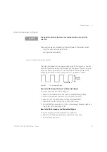
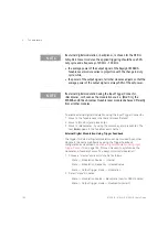
3 To pass the master trigger to the slaves, set up the mainframe through
the “Config” button under the screen:
Config -> Trigger -> Feedback
Note that the master laser must always be turned on, if one or more slaves
are on.
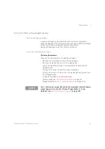
How to Increase Linewid th
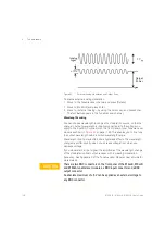
You can use coherence control to increase the linewidth of the optical
signal output from your Tunable Laser module.
Enabling the coherence control increases the linewidth of the optical
output signal to between 50 and 500 MHz (typically). Coherence control
greatly reduces interference effects and therefore improves the power
stability in sensitive test setups.
Some models also allow adjustment of the linewidth broadening with the
"Coherence level" setting. A level of 100% corresponds to minimal
broadening. The default level is usually a good setting.
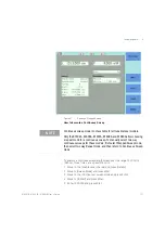
To enable coherence control:
1 Move to the Tunable Laser channel and press [Details].
2 Move to [
Mod
Src
] and press E
NTER
.
3 Move to <
Coherence
Ctrl.
>, Coherence Control, to increase linewidth
to approximately 500 MHz.
4 Press
Enter.
The text
CC
appears in the Tunable Laser channel.
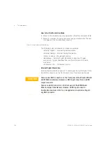
How to Set the Output Power of a Modulated Signal
All external modulation modes require you to set the output power. To set
the output power, see
How to Set the Output Power of a Modulated Signal
How to Configure the Modulation Output
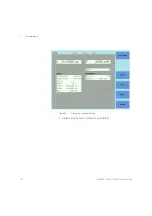
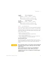
If your Tunable Laser module has a BNC output connector on its front
panel, to synchronize your external measuring equipment to the
modulation of the module:
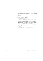
1 Move to the Tunable Laser channel and press
Menu
.
How to Set the BNC Output Line Mode as a Modulation Output
2 Move to <
BNC
Output
> and press [OK].
3 Move to <
Modulation
>, by using the cursor key. A TTL-level signal is
output, if the optical output is digitally modulated, that is, if you
choose <
Internal
>, <
External Digital
>, or <
Backplane
> as the chosen
Summary of Contents for 8163A
Page 17: ......
Page 86: ...8163A B 8164A B 8166A B User s Guide 85 Additional Information 2 Figure 47 MAC Address...
Page 99: ......
Page 133: ......
Page 213: ......
Page 298: ...8163A B 8164A B 8166A B User s Guide 297 Applications 10 Figure 183 Low Dynamic Range...
Page 310: ...8163A B 8164A B 8166A B User s Guide 309 Applications 10 Figure 190 Printed Results...
Page 313: ......
Page 345: ......
Page 453: ......

