Performance Verification 2
Series E4360 Service Guide
17
8
Disconnect the oscilloscope and connect an rms voltmeter in its
place. Do not disconnect the 50 ohm termination. Program the solar
array simulator to Fixed mode. Set the instrument as indicated in the
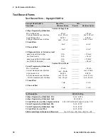
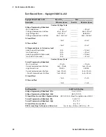
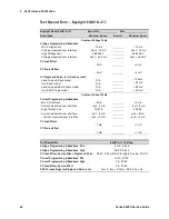
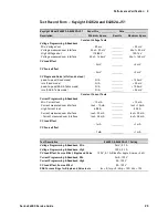
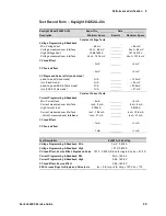
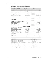
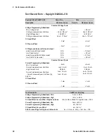
in the test record form under “CV Ripple and Noise” and enable the
output. Divide the reading of the rms voltmeter by 10. The result
should not exceed the rms limits in the test record form under “CV
Ripple and Noise, rms (Fixed mode)”.
9
Disconnect the load from the solar array simulator and check the
results again. The result should not exceed the rms limits in the test
record form under “CV Ripple and Noise, rms (Fixed mode)”.
10
Reconnect the load and program the solar array simulator to SAS
mode. Set the instrument as indicated in the in the test record form
under “SAS Curve Settings for Ripple and Noise” and enable the
output. Divide the reading of the rms voltmeter by 10. The result
should not exceed the rms limits in the test record form under “CV
Ripple and Noise, rms (SAS & Table mode)”.
11
Disconnect the load from the solar array simulator and check the
results again. The result should not exceed the rms limits in the test
record form under “CV Ripple and Noise, rms (SAS & Table mode)”.
Constant Current Tests
NOTE
Test each output channel individually. Refer to the appropriate test
record form for the instrument settings of the model you are checking.
Current Programming and Readback Accuracy
Test category = performance, calibration
This test verifies that the current programming and measurement
functions are within specifications.
1
Turn off the solar array simulator and connect the current shunt
directly across the output terminals. Connect the DMM directly
across the current shunt (see Test Setup figure B). Note that the
electronic load is not used in this portion of the test.
2
Turn on the solar array simulator and program the instrument
settings as indicated in the test record form under “Current
Programming
& Readback, Min Current”. The CC annunciator should
be on and the output voltage should be about zero.
3
Divide the voltage drop (DMM reading) across the current shunt by
the shunt resistance to convert to amperes and record this value
(Iout). Also, record the current measured over the interface. The
readings should be within the limits specified in the test record form
under “Current Programming and Readback, Min Current”.
4
Program the instrument settings as described in the test record form
under “Current Programming & Readback, High Current”.
Summary of Contents for E4360 Series
Page 1: ...Service Guide Keysight Technologies Series E4360 Modular Solar Array Simulator ...
Page 2: ......
Page 6: ......
Page 10: ......
Page 40: ......
Page 44: ...4 Disassembly 44 Series E4360 Service Guide ...
Page 64: ......
Page 72: ......


