background image

C

HAPTER

1

Product overview

Welcome to the Keysight M4100/APS-ONE-100 (APS System) Documentation.

An APS System provides next-generation ultra-high-performance Layer 4 - Layer 7 application
and security testing, TLS support and 100G Interfaces. Industry-proven BreakingPoint (BPS) is
the user interface application.

An APS system consists of one management node server (MN), one to ten compute node (CN)
servers, and the Keysight Cluster Operating System (KCOS).

l

The management node is used to manage the entire cluster of compute nodes and expose
administrative and test configuration functionalities to the user.

l

The compute nodes are used for generating custom traffic. They have QSFP28 interfaces for
connecting devices under test (DUTs). Compute nodes must have a functional management
node to operate.

l

Keysight Cluster Operating System (KCOS) is the APS base operating system. It provides a
command line interface (CLI) and a command shell to enable user control of the various
services. It is a purpose-built platform that provides essential services, including host
management, user access control, software upgrades and cluster orchestration.

– 6 –

Ixia APS-M1010/APS-ONE-100

Summary of Contents for Ixia APS-M1010

Page 1: ...202109300428 05 00 Ixia APS M1010 APS ONE 100 Release 9 17 Installation Guide ...

Page 2: ...to U S government customers under its standard commercial license which is embodied in its End User License Agree ment EULA a copy of which can be found at http www key sight com find sweula The license set forth in the EULA represents the exclusive authority by which the U S government may use modify distribute or disclose the Software The EULA and the license set forth therein does not require o...

Page 3: ...support ixiacom com EMEA Support 40 21 301 5699 support emea ixiacom com Greater China Region 400 898 0598 support china ixiacom com Hong Kong 852 30084465 support ixiacom com India Office 91 80 4939 6410 support india ixiacom com Japan Head Office 81 3 5326 1980 support japan ixiacom com Korea Office 82 2 3461 0095 support korea ixiacom com Singapore Office 65 6215 7700 support ixiacom com Taiwan...

Page 4: ...dd an account Click Accounts Other accounts Add an account Tap Accounts Other accounts Add an account To open the document in Outline view select View Outline To open the document in Outline view click View Outline To open the document in Outline view tap View Outline Select Protocols Click the Protocols tab Tap Protocols NA Double click the Client wizard Double tap the Client wizard Open the Pack...

Page 5: ... Compute Nodes 17 Chapter 8 Accessing the BreakingPoint user interface 18 IP Configuration using the KCOS CLI 19 Chapter 9 Getting Started with the BPS user interface 22 Open a new BPS session 22 Access the BPS Device manager and reserve ports for testing 23 Chapter 10 Connect DUTs for testing 24 Chapter 11 Add BPS ATI licenses 25 Chapter 12 How to install software packages 26 Chapter 13 Sample KC...

Page 6: ...o manage the entire cluster of compute nodes and expose administrative and test configuration functionalities to the user l The compute nodes are used for generating custom traffic They have QSFP28 interfaces for connecting devices under test DUTs Compute nodes must have a functional management node to operate l Keysight Cluster Operating System KCOS is the APS base operating system It provides a ...

Page 7: ...rmation about new features resolved customer issues known defects and workarounds if available APS M1010 APS ONE 100 CLI Reference Guide This guide describes the commands that make up the command line interface CLI for the APS M1010 APS CN100 BreakingPoint User Guide for APS Provides information on how to use BreakingPoint to set up run and customize tests Chapter 2 Related documentation 7 ...

Page 8: ...d in its own box 1 Management Node APS M1010 l A 1U Management Server l 2 power cords l 2 tool less rackmount slide rails l 1 Micro USB to USB cable Up to 10 Compute Nodes APS ONE 100 Each box contains l A compute node l 2 power cords l 1 Ethernet cable 3 ft l 2 tool less rackmount slide rails 8 Ixia APS M1010 APS ONE 100 ...

Page 9: ...ks 2 Detach the inner rail completely from the slide rail by pulling the white tab forward 3 After the inner rail is dislodged adjust the middle rail back to its original position by pushing the tab on the middle rail 4 Install the inner rail onto the system barebone Lock the keyholes and secure the screws on sides of the system 9 Ixia APS M1010 APS ONE 100 ...

Page 10: ...e outer rail bracket to the mounting frame Attach the outer rail assembling to the frame and press the bracket to form a rack on both ends Repeat to fully mount the bracket assembly on the other side Chapter 4 Rack mounting 10 ...

Page 11: ...6 Pull out the middle channel until the ball bearing retainer is locked forward Verify ball bearing retainer is locked forward Chapter 4 Rack mounting 11 ...

Page 12: ...7 Slide the release tab and push barebone into rack Make sure the barebone is completely installed onto the rack 8 Repeat this procedure until all components are rack mounted Chapter 4 Rack mounting 12 ...

Page 13: ...et LED indicator Reset button Luggage tag Shown on the preceding chassis image 2 x USB 3 0 Type a port Shown on the preceding chassis image The luggage tag can be pulled out from its recessed position as shown in the following image It displays The MN hostname in the format eagle APS M1 TW serial The MN password may also be displayed on the tag 13 Ixia APS M1010 APS ONE 100 ...

Page 14: ...Chapter 5 Front panel indicators 14 ...

Page 15: ...led C red 1 GE port that connects the APS M1010 management port to the lab network l Serial Connection Micro USB port labeled D green Baud 115200 data bits 8 stop bits 1 parity None flow control XON XOFF Compute Node APS ONE 100 l RJ 45 Port 1 white Connects Compute Node to a Management Node port 1 10 as shown in the image above l Sockets labeled A amber AC power cord connectors for primary and re...

Page 16: ...Ports and connectors that are not described may be available for use in a future release Chapter 6 Management Node and Compute Node ports and connectivity 16 ...

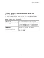
Page 17: ...ptacles Note the following power specifications Input Voltage 100 127VAC 200 240VAC 50 60Hz 15 10A x2 Power Supply Operating Mode 1 Redundant PSU 1 2 1 1 100 127VAC 200 240VAC 2 Single Supply PSU 1 1 0 100 127VAC 200 240VAC 3 Single Supply PSU 2 0 1 100 127VAC 200 240VAC Power Cords 15A 250V C13 TO C14 6 FT x2 Included Max Power Requirement 941 0110 1200W 941 0113 600W 17 Ixia APS M1010 APS ONE 10...

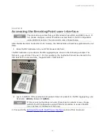
Page 18: ... provided on the MN luggage tag as shown in the following example The format is eagle APS M1 TW serial For this example the hostname that will be entered in the URL field for this unit would be eagle APS M1 TW21160104 2 Log in to BPS UI If the username and password are not present on the MN luggage tag use Username admin Password admin If this access method does not work there may be network issue...

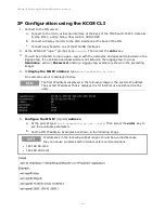
Page 19: ...ername admin Password admin a luggage tag example is shown in the preceding image 4 To display the MN IP address type kcos networking ip show An example output is displayed below The first IP address displayed in the following image is the system IP address The second IP address that is displayed is for internal use and should not be used 5 Configure the MN IP mgmt0 address a At the prompt type kc...

Page 20: ...IP settings troubleshoot connectivity issues you may want to run the following IP configuration commands a kcos networking hostname show b kcos networking hostname set new hostname c networking dns servers show d networking dns servers delete e networking dns servers add dns server ip Chapter 8 Accessing the BreakingPoint user interface 20 ...

Page 21: ...This page intentionally left blank 21 ...

Page 22: ...PS user interface Open a new BPS session 1 Log in to BPS as described in Accessing the BreakingPoint user interface The BPS dashboard will display 2 Select the New Session button under the BreakingPoint icon 22 Ixia APS M1010 APS ONE 100 ...

Page 23: ...he current cluster This process may take up to 15 minutes If your Compute Nodes do not appear in the Device Manager after 15 minutes see Troubleshooting Compute Node connectivity The displayed slot IDs correspond to the port number where the Compute Nodes are connected to the Management node For example a Compute Node connected to port 4 will be managed on slot 4 2 Reserve ports for testing See th...

Page 24: ...testing Each Compute Node supports up to two 100GE active ports for testing as shown in the following diagram Please connect ports 1 and 3 on each compute node QSFP28 interface to run emulated traffic 24 Ixia APS M1010 APS ONE 100 ...

Page 25: ...TER 11 Add BPS ATI licenses From the Device Manager access Control Center Administration Licensing Import the license files corresponding to the Compute Nodes that will be used 25 Ixia APS M1010 APS ONE 100 ...

Page 26: ...ment server l BreakingPoint Version aps bps x y z l KCOS Version aps kcos v w q 1 Open SSH to the MN and log in with admin admin 2 Copy the installation package from another system to the management node by using wget or scp Example wget ftp someserver aps kcos 9 17 9 20210505 081022 fa1344de offline tgz 3 Use the deployment service to install kcos deployment offline install name_of_offline_ packa...

Page 27: ...r APS System Check Compute Node connectivity 1 Connect to your APS System Management Node using SSH and log in with admin admin 2 Each node should show ready when listed using kcos system introspection nodes show 3 You can check the status of the slots and interfaces using netif kcos api Chapter 13 Sample KCOS debug commands 27 ...

Page 28: ...A Safety information Before setting up and using the unit read all of the safety information in this section and take all necessary measures to ensure your safety Safety symbols 29 28 Ixia APS M1010 APS ONE 100 ...

Page 29: ...iption CAUTION Indicates a hazardous situation that if not avoided could result in minor or moderate injury WARNING Indicates a hazardous situation that if not avoided could result in death or serious injury Additional icons are used to indicate specific types of warnings Laser radiation hazard warning Electrostatic discharge hazard warning High voltage hazard warning Hot surface hazard warning Mo...

Page 30: ...sistance 3 D documentation conventions 4 K keyboard interactions 4 M mouse interactions 4 P product support 3 S safety symbols 29 support services 3 T technical support 3 touch interactions 4 30 Ixia APS M1010 APS ONE 100 ...

Page 31: ...This information is subject to change without notice www keysight com Keysight Technologies 2021 ...

Reviews: