background image

12

Keysight N2791A/N2891A High-Voltage Differential Probes User Guide

Safety Information


Safety Information

Safety Notices

This apparatus has been designed and tested in accordance with IEC 

61010-031, Safety Requirements for Measuring Apparatus, and has been 

supplied in a safe condition. This is a Safety Class I instrument (provided 

with terminal for protective earthing). Before applying power, verify that 

the correct safety precautions are taken (see the following warnings). In 

addition, note the external markings on the instrument that are described 

under 

“Safety Symbols"

on page 13.

WARNING

Whenever it is likely that the ground protection is impaired, you must 

make the instrument inoperative and secure it against any unintended 

operation.

WARNING

Do not attempt internal service or adjustment.
Service should be carried out by a Keysight Technologies authorized 

service personnel. For any service needs, contact Keysight Technologies. 

WARNING

Do not install substitute parts or perform any unauthorized modification 

to the instrument.

WARNING

Capacitors inside the instrument may retain a charge even if the 

instrument is disconnected from its source of supply.

WARNING

Do not use the instrument in a manner not specified by the manufacturer.
If used in a manner not specified by the manufacturer, the protection 

provided by the probe assembly may be impaired.

Summary of Contents for N2791A

Page 1: ...User Guide N2791A 25 MHz and N2891A 70 MHz High Voltage Differential Probes ...

Page 2: ...er License Agreement EULA a copy of which can be found at http www keysight com find sweula The license set forth in the EULA represents the exclusive authority by which the U S gov ernment may use modify distribute or disclose the Software The EULA and the license set forth therein does not require or permit among other things that Key sight 1 Furnish technical information related to commercial c...

Page 3: ... Characteristics 10 Safety Information 12 Safety Notices 12 Safety Symbols 13 Safety Warnings and Cautions 13 Using the N2791A High Voltage Differential Probe 15 Using the N2891A High Voltage Differential Probe 16 N2791A Plots 17 N2891A Plots 21 Using the Accessories 25 Safety Hook and Alligator Clips 25 Safety Hook and High Voltage Alligator Clips 25 Extreme Temperature Probing Kit 26 N2791A Perf...

Page 4: ...igh Voltage Differential Probes User Guide Contents N2891A Performance Verification Procedures 32 DC Differential Gain Accuracy 32 Bandwidth 34 N2891A Performance Verification Test Record 35 Offset Zero Calibration Procedure 36 ...

Page 5: ... is damaged or the cushioning materials show signs of stress notify the carrier as well as your Keysight Technologies Sales Office Keep the shipping materials for the carrier s inspection The Keysight Technologies office will arrange for repair or replacement at Keysight Technologies option without waiting for claim settlement Cleaning the Probe Disconnect the probe and clean it with a soft damp c...

Page 6: ...pplications including power supply measurements and motor controls Both probes are compatible with any oscilloscope with a 1 MΩ BNC input The probes can be powered by any USB port on an oscilloscope or computer or by internal batteries 4x AA included with the probe The images below show some key parts of the N2891A probe body The N2791A has similar switches LEDs but they are arranged differently B...

Page 7: ...be For N2791A replacement accessories you can order the N2791 68700 Differential Probe Accessory Kit It includes Part Quantity N2791A 25 MHz Differential Probe 1 Safety Hook Red 1 Safety Hook Black 1 Alligator Clip Red 1 Alligator Clip Black 1 USB Power Cord 2 m 1 AA Battery 4 Trimmer Tool 1 Probe Resource Center Note 1 Part Quantity Safety Hook Red 1 Safety Hook Black 1 Alligator Clip Red 1 Allig...

Page 8: ... the N2891 68700 Differential Probe Accessory Kit It includes Part Quantity N2891A 70 MHz Differential Probe 1 Safety Hook Red 1 Safety Hook Black 1 High Voltage Alligator Clip Red 1 High Voltage Alligator Clip Black 1 USB Power Cord 2 m 1 AA Battery 4 Trimmer Tool 1 Probe Resource Center Note 1 Part Quantity Safety Hook Red 1 Safety Hook Black 1 High Voltage Alligator Clip Red 1 High Voltage Alli...

Page 9: ...s the same as listed in Table 1 Figure 1 N2791A Optional Accessories Extreme Temperature Probing Kit Table 1 N2791A Optional Accessories Accessory Qty Extreme Temperature Hook Tip Adapters Black 1 Extreme Temperature Hook Tip Adapters Red 1 Extreme Temperature Differential Extension Cables Black 1 Extreme Temperature Differential Extension Cables Red 1 Extreme Temperature Banana to Socketed Tip Ad...

Page 10: ...V at 10 1 attenuation 700 V at 100 1 attenuation 700 V at 100 1 attenuation 7000 V at 1000 1 attenuation Maximum Common Mode Input Voltage 70 V at 10 1 attenuation 700 V at 100 1 attenuation 70 V at 10 1 attenuation 700 V at 100 1 attenuation 7000 V at 10 1 attenuation 7000 V at 1000 1 attenuation Input Impedance 4 MΩ 10 pF each side to ground 8 MΩ 5 pF between inputs 4 MΩ 10 pF each side to groun...

Page 11: ...e Extension Cables 70 cm 27 5 inches N A Dimensions L x W x H 170 mm x 63 mm x 21 mm 6 7 inches x 2 5 inches x 0 83 inches 202 mm x 83 mm x 38 mm 8 0 inches x 3 3 inches x 1 5 inches Description Specifications Temperature Operating 5 C to 40 C Probe without the N7013 14A extreme temperature probing kit Operating 40 C to 85 C Probe with the N7013 14A extreme temperature probing kit Nonoperating 30 ...

Page 12: ...ge 13 WARNING Whenever it is likely that the ground protection is impaired you must make the instrument inoperative and secure it against any unintended operation WARNING Do not attempt internal service or adjustment Service should be carried out by a Keysight Technologies authorized service personnel For any service needs contact Keysight Technologies WARNING Do not install substitute parts or pe...

Page 13: ...s Do not use the N2891A probe above 5000 Vrms mains isolated 1000 1 attenuation or 500 Vrms mains isolated 100 1 attenuation between the two input leads Do not use the N2891A probe above 5000 Vrms mains isolated both 100 1 and 1000 1 attenuation settings between each input lead and earth WARNING Must be Grounded Before making connections to the input leads of this probe ensure that the output BNC ...

Page 14: ...r the supplied USB power cord WARNING For Indoor Use Only WARNING Periodically inspect the probe and probe wires to check for any damage Do Not Operate With Visible or Suspected Failures If you suspect there is damage have it inspected by a Keysight authorized service personnel CAUTION The probe cable and the extreme temperature extension cables are sensitive parts and therefore you should be care...

Page 15: ...n switch and specify the attenuation and probe configuration on your oscilloscope 4 Using the appropriate probe accessories connect the inputs to the circuit under test To replace batteries first slip off the cover Then slide the battery cover off on the rear of the probe NOTE TIP When measuring signals below 70 V switch the attenuation ratio to 10 1 in order to obtain a higher resolution signal w...

Page 16: ... attenuation switch see the picture on page 6 and specify the attenuation and probe configuration on your oscilloscope 4 Using the appropriate probe accessories connect the inputs to the circuit under test Slide the battery cover off the rear of the probe body NOTE TIP When measuring signals below 700 V switch the attenuation ratio to 100 1 in order to obtain a higher resolution signal with less n...

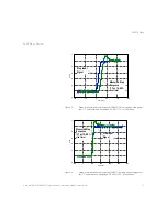
Page 17: ...0 90 10 1 attenuation Figure 3 Graph of normalized step response 50Ω 17 ns rising edge step genera tor 17 ns normalized rising edge 10 90 100 1 attenuation 100 50 0 50 100 150 0 2 0 0 2 0 4 0 6 0 8 1 1 2 Time ns Volts Step Input Signal Measured Step Response 17 ns 10 90 rise time 100 0 100 200 300 400 500 0 2 0 0 2 0 4 0 6 0 8 1 1 2 Time ns Volts Step Input Signal Measured Step Response 17 ns 10 9...

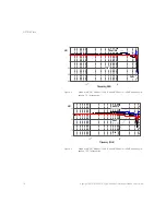
Page 18: ...dB Vin dB Vout 20dB and dB Vout Vin 20dB frequency re sponse 10 1 attenuation Figure 5 Graph of dB Vin dB Vout 40dB and dB Vout Vin 40dB frequency re sponse 100 1 attenuation 10 0 10 1 20 15 10 5 0 5 Frequency MH z dB Vout Vin Vout Vin 10 0 10 1 10 7 5 5 2 5 0 2 5 5 Frequency MH z dB Vout Vin Vout Vin ...

Page 19: ...igure 6 Graph of dB Vout Vin 20dB frequency response when inputs driven in common mode common mode rejection 10 1 attenuation Figure 7 Magnitude plot of probe input impedance versus frequency differential single ended 10 2 10 3 10 4 10 5 10 6 10 7 10 8 100 80 60 40 20 Frequency H z dB ...

Page 20: ...t N2791A N2891A High Voltage Differential Probes User Guide N2791A Plots Figure 8 Typical derating plot of the absolute maximum input voltage in common mode 10 6 10 7 100 300 500 700 900 1100 Frequency H z V rm s ...

Page 21: ...ion Figure 10 Graph of normalized step response 50 Ω 10 ns rising edge step genera tor 10 ns normalized rising edge 10 90 1000 1 attenuation 20 0 20 40 60 80 100 0 2 0 0 2 0 4 0 6 0 8 1 1 2 Time nS Normalized Step Response V Step Input Signal Probe Step Response 10 ns 10 90 rise time 20 0 20 40 60 80 100 0 2 0 0 2 0 4 0 6 0 8 1 1 2 Time nS Normalized Step Response V Step Input Signal Probe Step Re...

Page 22: ...Graph of dB S21 40 dB frequency response 100 1 attenuation Figure 12 Graph of dB S21 60 dB frequency response 1000 1 attenuation 10 0 10 2 10 4 10 6 10 8 35 30 25 20 15 10 5 0 5 Frequency Hz Normalized S21 40dB 10 0 10 2 10 4 10 6 10 8 16 14 12 10 8 6 4 2 0 2 4 Frequency Hz Normalized S21 60dB ...

Page 23: ...Plots Figure 13 Graph of dB S21 40 dB frequency response when inputs driven in com mon mode common mode rejection 100 1 attenuation Figure 14 Magnitude plot of probe input impedance versus frequency single ended 10 2 10 4 10 6 10 8 90 80 70 60 50 40 30 20 10 Frequency Hz CMRR dB ...

Page 24: ...ential Probes User Guide N2891A Plots and differential Figure 15 Typical derating plot of absolute maximum input voltage in common mode Figure 16 Input impedance equivalent circuit diagram 10 5 10 6 10 7 10 8 10 1 10 2 10 3 10 4 Frequency Hz Vrms ...

Page 25: ...afety Hook and Alligator Clips Use the safety hooks to clamp onto smaller components and use the alligator clips to clamp onto thicker gauge devices The following accessories are supplied with the N2891A probe and with the N2891 68700 Accessory Kit Safety Hook and High Voltage Alligator Clips Use the safety hooks to clamp onto smaller components and use the alligator clips to clamp onto thicker ga...

Page 26: ... tip adapters black and red One pair of extreme temperature banana to socketed tip adapters for connecting to 0 025 square pins black and red The N7014A extreme temperature probing kit includes One pair of extreme temperature banana to socketed tip adapters for connecting to 0 025 square pins black and red NOTE The N7013 14A extreme temperature probing kit is not supplied with the probe You can or...

Page 27: ... extreme temperature kit to the N2791A probe 1 Connect the red and black extreme temperature differential extension cables to the existing probe cables Figure 17 Connecting the Extreme Temperature Differential Extension Cables 2 Connect the red and black extreme temperature hook tip adapters to the extreme temperature differential extension cables which are already connected to the existing probe ...

Page 28: ... the Extreme Temperature Hook Tip Adapters Or Connect the red and black extreme temperature banana to socketed tip adapters to the extreme temperature differential extension cables which are already connected to the existing probe cables Figure 19 Connecting the Extreme Temperature Banana to Socketed Tip Adapters ...

Page 29: ...cope 4 Connect the active head channel 1 from the Fluke 9500B to channel 1 of the oscilloscope Set the calibrator channel 1 to 0 1V peak to peak amplitude and 1 KHz square wave 1 MΩ load enable the output 5 Select the amplitude measurement on the oscilloscope and record the DC amplitude approximately 100 mV of the square wave This measurement is only the oscilloscope 6 Disable the Fluke calibrator...

Page 30: ... 10 into just the amplitude of the oscilloscope Verify that the probe gain accuracy is 2 scope gain accuracy 15 Disable the calibrator output and leave the setup connected for the next procedure Bandwidth 1 Connect the 50 Ω BNC feed through adapter to the calibrator s active head channel 1 2 Attach the BNC f to banana post adapter to the BNC feed through adapter 3 Attach the differential probe inp...

Page 31: ...___________ Certification Date ________________ Tested By _______________________ Recommended Test Interval 1 Year Recommended Date of Next Certification _________ Certification Temperature _____________________ _________________________________ _________________________________ Test Probe Settings Limits Results Gain 100 1 98 mV to 102 mV Gain 10 1 98 mV to 102 mV Bandwidth 10 1 Greater than or e...

Page 32: ...al Generator Precision DC voltage source Amplitude accuracy less than or equal to 0 25 1 MΩ 50Ω selectable load Sine wave greater than or equal to 25 MHz Fluke 9500B Signal source for DC gain and bandwidth BNC Adapter BNC f to Dual Banana m Adapter Keysight 1251 2277 Interconnection between probe and generator 50 Ω BNC Feed Through Adapter 50 Ω precision feed through Keysight 11048C Termination be...

Page 33: ...ement is only the oscilloscope 6 Disable the Fluke calibrator output disconnect the channel 1 active head from channel 1 of the oscilloscope 7 Connect the output of the N2891A probe to channel 1 of the oscilloscope 8 Attach the BNC adapter to the Fluke channel 1 active head 9 Attach the differential probe input leads by clipping the alligator clamp to the BNC adapter banana post 10 Set the probe t...

Page 34: ...NC adapter banana post 4 Set the probe to 100 1 attenuation 5 Set the volts division on channel 1 of the oscilloscope to 10 mV div and seconds division to 20 ns div Set the trace to the center of the oscilloscope Input impedance should be set to 1 ΜΩ Disable average mode 6 Set the calibrator to sine wave 5 V peak to peak amplitude Set the frequency to 70 MHz 50 Ω load 7 Write down the peak to peak...

Page 35: ...__________ Certification Date ________________ Tested By _______________________ Recommended Test Interval 1 Year Recommended Date of Next Certification _________ Certification Temperature _____________________ _________________________________ _________________________________ Test Probe Settings Limits Results Gain 100 1 98 mV to 102 mV Gain 1000 1 98 mV to 102 mV Bandwidth 10 1 Greater than or ...

Page 36: ...probe attenuation ratio to 10 1 for N2791A or 100 1 for N2891A 2 Short the and probe inputs together with the hook tips 3 Turn on power to the oscilloscope and the probe and leave them on for 30 minutes so they can stabilize 4 Press Default Setup and Auto Scale on the oscilloscope 5 Press the channel 1 button then press the Probe softkey and then set the units to Volt and the probe attenuation to ...

Page 37: ...Keysight N2791A N2891A High Voltage Differential Probes User Guide 37 ...

Page 38: ...This information is subject to change without notice Keysight Technologies 2018 N2791 97008 December 2018 www keysight com ...

Reviews: