30/44
Scienlab Regenerative AC Emulator
–
Keysight SL1200A Series
–
Operating Instructions
3 Connection and Assembly
HSI Uplink / HIS Downlink
•
On the top of the Output Box on the rear side
•
Ethernet connection ports (RJ45)
•
For parallel connection director/follower systems
(see
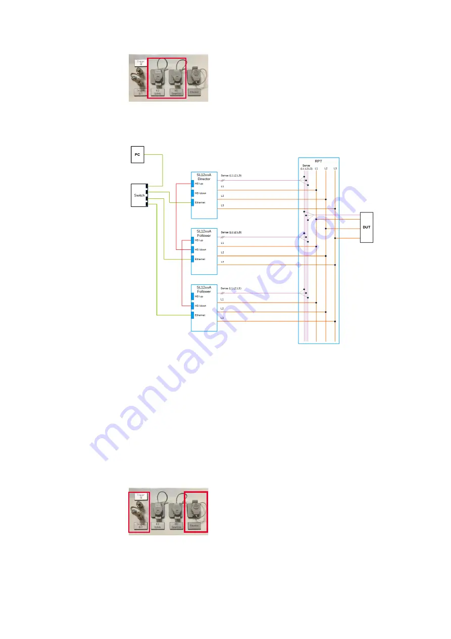
The following Figure 5 shows an example for a parallel connection via Re-
mote Power Terminal (RPT).
Figure 5: Schematic for parallel connection (connection via remote power termi-
nal (RPT) as an example)
For more information please refer to the help file of the PC software
SL1200A Regenerative AC Emulator Soft Front Panel on
Connecting signal and control lines
Communication interfaces
Additional signal and control connections can be found the roof of the
output box, on the rear side of the system. Here are communication inter-
faces (RJ45 sockets) for the connection of an operating computer (Ether-
net connection port) or interfaces (BNC sockets) for trigger signals.
Ethernet Interface
•
On the top of the Output Box on the rear side
•
Communication interface to the operating PC
Trigger In / Out, BNC sockets
•
On the top of the Output Box on the rear side
•
Freely usable interface (e. g. for external oscilloscope)
•
Input: reaction to trigger signals
•
Output: sending a trigger signal on specified events
Summary of Contents for SL1200A Series
Page 2: ......


