background image

62

Keysight E1406A Command Module Service Guide

Verification Tests

Test F-7: Serial Port Information

Example Program

This program uses the commands listed in the Description section to return 
information on the current Command Module Serial (RS-232) Port settings.

1!Test F-7: Serial Port Information
2!
10Assign @Addr to 70900!Assign @Addr to cmd module
20OUTPUT @Addr;"DIAG:COMM:SER:OWN?"!Query serial port ownership
30ENTER @Addr;Own$
40OUTPUT @Addr;"SYST:COMM:SER:BAUD?"! Query baud rate
50ENTER @Addr;Baud
60OUTPUT @Addr;"SYST:COMM:SER:CONT:DTR?"!Query DTR mode line
70ENTER @Addr;Dtr$
80OUTPUT @Addr;"SYST:COMM:SER:CONT:RTS?"!Query RTS mode line

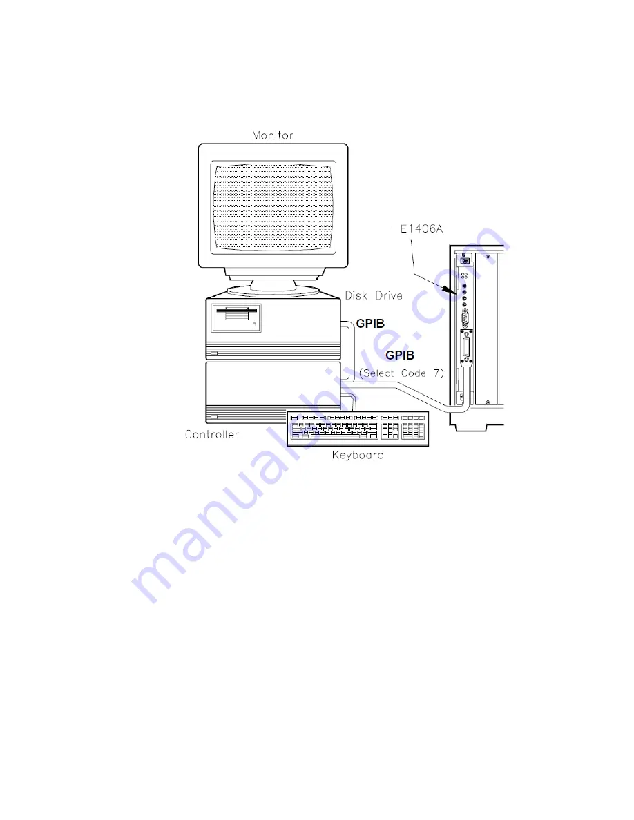
Figure 2-14

Test F-7: Serial Port Info Connections

Summary of Contents for VXI bus 75000 C Series

Page 1: ...Keysight E1406A Command Module Service Guide 75000 Series C...

Page 2: ......

Page 3: ...IGHT DISCLAIMS ALL WAR RANTIES EITHER EXPRESS OR IMPLIED WITH REGARD TO THIS MANUAL AND ANY INFORMATION CONTAINED HEREIN INCLUDING BUT NOT LIMITED TO THE IMPLIED WARRANTIES OF MER CHANTABILITY AND FIT...

Page 4: ...perform proce dures involving cover or shield removal unless you are qualified to do so DO NOT operate damaged equipment Whenever it is possible that the safety protection features built into this pr...

Page 5: ...ly understood and met A WARNING denotes a hazard It calls attention to an operating pro cedure or practice that if not cor rectly performed or adhered to could result in personal injury or death Do no...

Page 6: ...6...

Page 7: ...ion Tests Introduction 19 Command Module Configuration 20 Factory Settings 20 Some Command Module Definitions 22 Resource Manager Slot 0 Device 22 Logical Address GPIB Address 22 Commander Servant Are...

Page 8: ...lts 45 Test F 4 Table Memory Information 46 Description 46 Configuration Table Addresses 46 Command Module Memory Addresses Sizes 46 Set Up Equipment 46 Example Program 47 Typical Results 51 Test F 5...

Page 9: ...iled and SYSFAIL LEDs ON 74 5 Failed LED ONLY ON 74 6 Check Command Module 75 Assembly Disassembly Instructions 76 Repair Maintenance Guidelines 85 ESD Precautions 85 Soldering Printed Circuit Boards...

Page 10: ...x Keysight E1406A Command Module Service Guide...

Page 11: ...hows a typical E1406A Command Module See Keysight 75000 Series C Service Documentation page 4 for a list of manuals that describe mainframe and command module operation and hardware The information in...

Page 12: ...s for service trained personnel who are familiar with electronic circuitry and are aware of the hazards involved To avoid personal injury or damage to the instrument do not perform procedures in this...

Page 13: ...side of the main s supply USE PROPER FUSES For continued protection against fire hazard replace the line fuse s only with fuses of the same current rating and type such as normal blow time delay etc...

Page 14: ...mental limits recommended test equipment Specifications See Appendix A Specifications in the Keysight E 1406A Command Module User s Manual for command module specifications Serial Numbers Figure 1 2 s...

Page 15: ...fice A list of these offices is at the back of this manual Operating Storage Environments The Command Module should be stored in a clean dry environment See Table 1 3 for recommended command module op...

Page 16: ...dule Table 1 4 Keysight E1406A Command Module Recommended Test Equipment Instrument Requirements Recommended Model Use1 Controller GPIB GPIB compatibility as defined by IEEE Standard 488 1987 and the...

Page 17: ...Keysight E1406A Command Module Service Guide 17 Inspection Shipping General Information Figure 1 3 Initial Incoming Inspection Guidelines...

Page 18: ...nd module to an Keysight Technologies Sales and Support Office or to a Service Center We recommend you use the same shipping materials as those used in factory packaging available from Keysight Techno...

Page 19: ...d adapters required See Table 1 4 Keysight E1406A Command Module Recommended Test Equipment for test equipment requirements Do not perform any of the verification tests in this chapter unless you are...

Page 20: ...ng Function 1 VME System Controller Slot 0 Enable Disable Enabled 0 Disabled 1 Enabled Enabled When the VME System Controller and Slot 0 Enable Disable switches are enabled the command module function...

Page 21: ...ests Figure 2 1 Command Module Switches Factory Settings Be sure switches are COMPLETELY seated in the proper position Switches may appear to be in the correct position but may not be fully seated One...

Page 22: ...ger is no longer used The resource manager identifies all installed plug in modules sets commander servant hierarchies performs A24 A32 mapping allocates interrupt lines starts system operation During...

Page 23: ...condary GPIB Address Commander Servant Areas In a VXIbus system the servant area identifies the modules servants that are controlled by other modules commanders The Logical Address switch sets the com...

Page 24: ...24 Keysight E1406A Command Module Service Guide Verification Tests Command Module Configuration Figure 2 3 Example Command Servant Hierarchy...

Page 25: ...fails see Chapter 4 Service for further tests information Test S 1 GPIB Power On Test Description This test uses the SYST ERR command for the command modules GPIB power on test A 0 No error return ind...

Page 26: ...eturns an error message for each error detected In this case see Chapter 5 Error Messages for an explanation of the error s 1 Test S 1 GPIB Power On Self Test 2 10CLEAR SCREEN 20 ASSIGN Addr to 70900...

Page 27: ...all modules except command module from mainframe 110 PRINT 3 Turn mainframe power ON 120 PRINT 4 Wait at least 5 seconds before running the test 130 DISP Press Continue to run the GPIB power on test 1...

Page 28: ...d module s RS 232 port Pressing CTRL S on the terminal keyboard pauses the sequence and pressing CTRL Q resumes the sequence Once the sequence is paused it remains paused until CTRL Q is pressed Set u...

Page 29: ...er Servant hierarchy ladd 0 cmdr ladd 1 ladd 8 cmdr ladd 0 ladd 16 cmdr ladd 0 ladd 32 cmdr ladd 24 ladd 64 cmdr ladd 24 Validating Commander Servant hierarchy Commander ladd 24 granted device ladd 32...

Page 30: ...A24 addresses to access the memory located on the modules at logical addresses 0 24 and 64 Note that the offset is specified in hexadecimal and the size is specified in bytes For this particular syst...

Page 31: ...F 1 Front Panel Outputs Checks outputs from the Trig Out Port and the Clk Out Port F 2 General System Information Returns command module addresses number of devices in the system and system version t...

Page 32: ...line as a trigger source For each TTLTrg ECLTrg trigger line the Trig Out port level should start at 5V then go to 0V for two seconds then go back to 5V C Trig In Port Source Test Checks the Trig In...

Page 33: ...t F 1 Front Panel Outputs Verification Tests Set up Equipment Turn mainframe power OFF Connect oscilloscope to command module see Figure 2 7 Set up oscilloscope see Figure 2 7 Turn mainframe power ON...

Page 34: ...Out port level ON 100 WAIT 2 Wait 2 seconds 110 OUTPUT Addr OUTP EXT LEV OFF Set Trig Out port level OFF 120 CLEAR SCREEN 130 PRINT Part B TTL ECL Trigger Line Source Test 140 PRINT 150 PRINT Connect...

Page 35: ...e Trig Out port 400 DISP Press Continue when ready to run this test 410 PAUSE 420 CLEAR SCREEN 430 FOR I 0 TO 9 440OUTPUT Addr OUTP Trg_sour I STAT ON Set TTLTrg ECLTrg line STATE ON 450OUTPUT Addr OU...

Page 36: ...INT Connect oscilloscope to command module Clk Out port 600 DISP Press Continue when ready to run this test 610 PAUSE 620 CLEAR SCREEN 630 END Typical Results See Figure 2 6 for oscilloscope displays...

Page 37: ...mmand module GPIB address VXI CONF DNUM Number of devices in the system VXI CONF LADD Device logical addresses SYST VERS SCPI version for compliance SYST DATE Current date setting SYST TIME Current ti...

Page 38: ...r Syst_date 130OUTPUT Addr SYST TIME Query current time setting 140ENTER Addr Syst_time 150PRINT Test F 2 General System Information 160PRINT 170PRINT Command module GPIB address Cmd_addr 180PRINT Num...

Page 39: ...tween 1 and 255 1 device has no logical address Commander s logical address Integer between 1 and 255 1 device has no commander or commander is unknown Interrupt handlers Comma separated list of 7 int...

Page 40: ...967295 Base address for A32 registers on device 1 device has no A32 memory A16 Memory Size Integer between 1 and 65535 Number of bytes reserved for A16 registers 1 device has no A24 memory A24 Memory...

Page 41: ...ses VXI CONF HIER and VXI CONF INF to return current hierarchy configuration and static information for the module at the logical address you select 1 Test F 3 Hierarchy Device Information 2 3 Query s...

Page 42: ...e at sel Logical Address 120 ENTER Addr Hier 130 INTEGER Scn1 Fnd1 140 Scn1 1 150 FOR I 1 TO 17 STEP Scn1 Loop to find individual values 160 Fnd1 POS Hier Scn1 170 Hinf I Hier Scn1 Fnd1 1 180 Scn1 Scn...

Page 43: ...nd POS Inf Scn 490Rinf I Inf Scn Fnd 1 500Scn Scn Fnd 510NEXT I 520PRINT VXI CONF INF Command Results 530PRINT 540 PRINT Logical Address Rinf 1 550 PRINT Manufacturer ID Rinf 2 560 PRINT Model Code Ri...

Page 44: ...5 0 Interrupt Handler 6 0 Interrupt Handler 7 0 Interrupter 1 0 interrupter is not configured Interrupter 2 0 Interrupter 3 0 Interrupter 4 0 Interrupter 5 0 Interrupter 6 0 Interrupter 7 0 Pass Faile...

Page 45: ...A16 Memory Offset 1 device has no A16 memory A24 Memory Offset 2097152 A24 registers base address A32 Memory Offset 1 device has no A32 memory A16 Memory Size 1 device has no A16 memory A24 Memory Siz...

Page 46: ...ETAB Extender Device Table Address VXI CONF ITAB Interrupt Line Allocation Table Address VXI CONF MTAB A24 A32 Address Allocation Table Address Command Module Memory Addresses Sizes DIAG NRAM ADDR NRA...

Page 47: ...and memory addresses sizes 1 Test F 4 Table Memory Information 2 3 Get Configuration Table Information 10 ASSIGN Addr to 70900 Assign Addr to cmd module 20 DIM Dvr_list 1000 30 OUTPUT Addr VXI CONF C...

Page 48: ...Addr DIAG RDIS CRE Current RDISK size bytes 220 ENTER Addr Rdis_cre 230 OUTPUT Addr DIAG RDIS CRE MAX Maximum RDISK size bytes 240 ENTER Addr Rdis_max 250 OUTPUT Addr DIAG DRAM AVA Remaining DRAM ava...

Page 49: ...0Scan Scan Found 590ELSE 600END IF 610UNTIL NOT Found 620PRINT TAB 9 Dvr_list Scan Scan 50 630PRINT 640PRINT 650PRINT 660PRINT TESTING FLASH ROM 670PRINT 680 PRINT Step 1 Turn OFF the mainframe 681 PR...

Page 50: ...the Run Load Switch on the Keysight E1406A Command Module in the LOAD position 940 PRINT Step 11 Turn ON the Mainframe 950 PRINT Step 12 Press CONTINUE to continue program execution 960 PAUSE 970 WAI...

Page 51: ...namic Configuration Table Address 0 Extender Device Table Address 0 Interrupt Line Allocation Table Address 0 A24 A32 Address Allocation Table Address 0 Command Module Memory NRAM starting address 0 C...

Page 52: ...mmand Module Service Guide Verification Tests Test F 4 Table Memory Information Flash ROM Created for Drivers 0 Flash ROM set to maximum Flash ROM Available 1048576 Flash ROM Size 1048576 Flash ROM Cr...

Page 53: ...ts in the Keysight E1406A Command Module User s Manual for interrupt and status information Interrupt Information DIAG INT SETn State of interrupt line n Status Information STAT OPER COND State of Con...

Page 54: ...terrupt lines and register status 1 Test F 5 Interrupt Status Information 2 3 Get Interrupt Information 10ASSIGN Addr to 70900 Assign Addr to cmd mod 20DIM Int_set 7 3 30FOR I 1 TO 7 Loop to find stat...

Page 55: ...mation 180PRINT 190PRINT State of interrupt line 1 Int_set 1 200PRINT State of interrupt line 2 Int_set 2 210PRINT State of interrupt line 3 Int_set 3 220PRINT State of interrupt line 4 Int_set 4 230P...

Page 56: ...rupt line 2 OFF State of interrupt line 3 OFF State of interrupt line 4 OFF State of interrupt line 5 OFF State of interrupt line 6 OFF State of interrupt line 7 OFF Status Information State of Condit...

Page 57: ...EV ECLTrg Line n Logic Level OUTP ECLT n SOUR ECLTrg Line n Source OUTP ECLT n STAT ECLTrg Line n State ON or OFF TTLTrg Trigger Lines n 0 to 7 OUTP TTLT n LEV TTLTrg Line n Logic Level OUTP TTLT n SO...

Page 58: ...cription section to return information on the ECLTrg and TTLTrg trigger lines and on the Command Module Trig Out port 1 Test F 6 Triggering Information 2 10Assign Addr to 70900 Assign Addr to Cmd Mod...

Page 59: ...UR Query TTLTrg lines 0 7 source 160ENTER Addr Tsour I 170OUTPUT Addr OUTP TTLT VAL I STAT Query TTLTrg lines 0 7 state 180ENTER Addr Tstat I 190NEXT I 191 Get Trig Out Port Information 200OUTPUT Addr...

Page 60: ...nd the Trig Out port set at level 0 no source and state 0 Test F 6 Triggering Information Level Source State ECLTrg Trigger Line 0 0 NONE 0 ECLTrg Trigger Line 1 0 NONE 0 TTLTrg Trigger Line 0 0 NONE...

Page 61: ...ER CONT RTS RTS mode line SYST COMM SER BITS Bits setting SYST COMM SER SBIT Number of stop bits SYST COMM SER PACE THR STAR STARt threshold level SYST COMM SER PACE THR STOP STOP threshold level SYST...

Page 62: ...rial RS 232 Port settings 1 Test F 7 Serial Port Information 2 10Assign Addr to 70900 Assign Addr to cmd module 20OUTPUT Addr DIAG COMM SER OWN Query serial port ownership 30ENTER Addr Own 40OUTPUT Ad...

Page 63: ...arity type checking 210ENTER Addr Typ 220OUTPUT Addr SYST COMM SER TRAN AUTO Query transmit receive protocol 230ENTER Addr Auto 240OUTPUT Addr SYST COMM SER PACE PROT Query receive pacing protocol 250...

Page 64: ...al results follow for a command module RS 232 serial port Test F 7 Serial Port Information Serial port ownership SYST Transmit receive baud rate 9600 Current mode of DTR line ON Current mode of RTS li...

Page 65: ...t number Replaceable Parts Lists Table 3 2 lists replaceable parts for the Keysight E 1406A Command Modules See Component Locators Figures 3 1 and 3 2 for locations of parts in Table 3 2 Table 3 3 sho...

Page 66: ...TION STANDOFF HEX 312 IN LG 4 40 THD STANDOFF HEX 15 MM LG M3 0 X 0 5 THD RFI STRIP FINGERS BE CU TIN PLATED FRONT PANEL COMMAND MODULE SCREW MACHINE M3 X 0 5 14MM LG FLAT HEAD SCREW MACHINE M3 X 0 5...

Page 67: ...Manufacturers Mfr Code Manufacturer Name Manufacturer Address Zip Code 00779 05791 06776 18873 26742 27264 28480 30817 59730 74163 74970 75915 76381 78189 81073 81312 83486 97525 98291 AMP INC LYN TR...

Page 68: ...mand Module Service Guide Replaceable Parts Component Locators Component Locators Figures 3 1 and 3 2 show locations of selected replaceable parts for the Keysight E 1406A Command Module Figure 3 1 Ke...

Page 69: ...Keysight Keysight E1406A Command Module Service Guide 69 Component Locators Replaceable Parts Figure 3 2 Keysight E1406A A1 PCA Replaceable Parts...

Page 70: ...70 Keysight Keysight E1406A Command Module Service Guide Replaceable Parts Component Locators...

Page 71: ...mmand Module is module replacement Before replacing an Keysight E1406A Command Module check fuses F1 through F5 on the A1 Printed Circuit Assembly PCA and or the replaceable mechanical parts listed in...

Page 72: ...Step 3 Step 4 or Step 5 For NORMAL power on the RS 232 terminal display shows A kernel test that tests RAM ROM and the microprocessor monitors the ACFAIL line and then calls the Resource Manager to ch...

Page 73: ...Keysight E1406A Command Module Service Guide 73 Troubleshooting Service Figure 4 1 E1406A Command Module Troubleshooting...

Page 74: ...N and rerun Step 2 Check LEDs and Terminal Display 4 Failed and SYSFAIL LEDs ON The command module has failed the power on self test OR the module could not complete initialization of one or more inst...

Page 75: ...the switch settings fuses and or mechanical parts appear to be good disconnect and then reconnect the battery connector Reassemble and reinstall the command module and turn mainframe power ON Then re...

Page 76: ...nal Display Assembly Disassembly Instructions This section shows how to disassemble and reassemble an Keysight E1406A Command Module See Figure 4 2 to prepare a command module for disassembly To perfo...

Page 77: ...Keysight E1406A Command Module Service Guide 77 Assembly Disassembly Instructions Service...

Page 78: ...78 Keysight E1406A Command Module Service Guide Service Assembly Disassembly Instructions...

Page 79: ...Keysight E1406A Command Module Service Guide 79 Assembly Disassembly Instructions Service...

Page 80: ...ly Disassembly Instructions Be sure switches are COMPLETELY seated in the proper position Switches may appear to be in the correct position but may not be fully seated One way to ensure that switches...

Page 81: ...Keysight E1406A Command Module Service Guide 81 Assembly Disassembly Instructions Service...

Page 82: ...82 Keysight E1406A Command Module Service Guide Service Assembly Disassembly Instructions...

Page 83: ...Keysight E1406A Command Module Service Guide 83 Assembly Disassembly Instructions Service...

Page 84: ...84 Keysight E1406A Command Module Service Guide Service Assembly Disassembly Instructions...

Page 85: ...grip socket Instead use a small screwdriver to pry the device up from one end Slowly lift the device up one pair of pins at a time After you remove a CMOS device from a module place the device onto a...

Page 86: ...mounting holes When using a suction device be sure the equipment is properly grounded to prevent electrostatic discharge from damaging CMOS devices Post Repair Safety Checks After making repairs to c...

Page 87: ...3 for location note the model number on the upper label of the bottom shield of the module b If the model label has been removed from the bottom shield of the command module you will need to look at t...

Page 88: ...ommand Module Service Guide Service Returning an Keysight E1406A 2 Ship the Module to Keysight Technologies Package the module and ship it to Keysight Technologies See Chapter 1 General Information fo...

Page 89: ...ion Language Related Errors 100 to 499 Command Errors 100 to 199 The instrum ent cannot understand or execute the command Execution Errors 200 to 299 The instrum ent is incapable of doing the action o...

Page 90: ...256 Create array for error message 20REPEATRepeat until no errors in queue 30OUTPUT 70900 SYST ERR Read error message 40ENTER 70900 Err_msg Enter results 50PRINT Err_msg Display results 60UNTIL Err_ms...

Page 91: ...ich a param eter is required 113 UNDEFINEDHEADER Com m and header was incorrectly specified 123 NUMERICOVERFLOW A param eter specifies a value greater than the com m and allows 128 NUMERICDATA NOTALLO...

Page 92: ...urce manager finds the PASSED bit false The test is done five seconds after power on or when the operating system has determined that SYSFAIL is not asserted 2 UNABLE TO COMBINE DEVICE A device cannot...

Page 93: ...le s logical address is not a multiple of 8 or is not part of a virtual instrument Secondary GPIB addresses are only given to devices with logical addresses that are a multiple of eight 12 INVALID UDE...

Page 94: ...erial protocol violation due to a word serial command The command module checks for ERR asserted before and after sending a word serial command to a message based device If ERR is asserted before the...

Page 95: ...cation table is invalid or the address block exceeds FFFFFFh in A24 memory 34 UDEF MEMORY BLOCK UNAVAILABLE The memory block specified in the A24 A32 address allocation table has already been assigned...

Page 96: ...ery may be disconnected or discharged 46 MESG BASED OPEN ACCESSFAILED IBASIC or GPIB access to a message based device failed because of a device failure The resource manager tries to open a path betwe...

Page 97: ...has an invalid base or size 58 INVALID UDEF A16 WINDOW A user defined A16 window violates the VXI 6 specification has an invalid base or size 59 INVALID UDEF A24 WINDOW A user defined A24 window viola...

Page 98: ...r a 16 bit read or write Always use an even address for 16 bit word accesses 2005 NO CARD AT LOGICAL ADDRESS A non existant logical address was specified with the VXI READ or VXI WRITE command 2016 BY...

Page 99: ...ition 2118 INVALID COMMANDER LOGICAL ADDRESS A device does not have a valid commander 2119 BNO FAILED Sending a BEGIN Normal Operation command to a device failed 2120 WRITE READY TIMEOUT A message bas...

Page 100: ...ter is a device that is not an interpreter 2142 INVALID UDEF INTR TABLE The interpreter table valid flag is not 1 2143 INVALID UDEF MEM TABLE The valid flag in the Memory table is not set to 1 2144 IN...

Page 101: ...ATA There are more than 254 records in the Extender table 2163 UNSUPPORTED UDEF TTL TRIGGER There is an Extender table TTL trigger entry for a device which does not support TTL triggers 2164 UNSUPPORT...

Page 102: ...ized GPIB IRQ SYSTEM ERROR Uninitialized GPIB BI SYSTEM ERROR Uninitialized GPIB BO SYSTEM ERROR Uninitialized GPIB REN SYSTEM ERROR Uninitialized UART IRQ SYSTEM ERROR Unused Jmp Tbl Entry Call SYSTE...

Page 103: ...ized TRAP12 SYSTEM ERROR Uninitialized TRAP13 SYSTEM ERROR Uninitialized TRAP14 SYSTEM ERROR Uninitialized TRAP15 Defective gate array MC 68000 chip or ROM Power On Diagnostics Error Messages Testing...

Page 104: ...ty Register in PSOS Tick Register on RS232 IC on Key Board Scan IC Bus Error Timeout Interrupt Control Register No Clock Tick Interrupt No Pacer Interrupt Defective gate array No UART Interrupt Defect...

Page 105: ...ster State Bad Defective CPU SYSTEM ERROR Bus Error VXI LADD n Defective VXIbus card Logical Address n SYSTEM ERROR Bus Error in VME A16 Space SYSTEM ERROR Bus Error in VME A24 Space Defective ROM CPU...

Page 106: ...106 KeysightE1406A Command Module Service Guide Error Messages Introduction...

Page 107: ...of the E1406A Service Manual Program Rev A 01 00 7 30 96 include stdio h include string h include visa h Function Prototypes void power_on_test ViSession vi ViStatus x void front_panel_outputs ViSessi...

Page 108: ...n printf 0 for Test S 1 GPIB Power On Test n printf 1 for Test F 1 Front Panel Outputs n printf 2 for Test F 2 General System Information n printf 3 for Test F 3 Hierarchy Device Information n printf...

Page 109: ..._information cm err break case 5 interrupt_status_information cm err break case 6 triggering_information cm err break case 7 serial_port_information cm err break case 8 printf n End of testing n break...

Page 110: ...f err VI_SUCCESS err_handler cm err printf s err_msg while err_msg 1 0 return TEST F 1 Front Panel Outputs void front_panel_outputs ViSession cm ViStatus err int result i fflush stdin printf n Front P...

Page 111: ...TTLT u STAT ON n i if err VI_SUCCESS err_handler cm err err viPrintf cm OUTP TTLT u SOUR INT n i if err VI_SUCCESS err_handler cm err err viPrintf cm OUTP EXT STAT ON n if err VI_SUCCESS err_handler c...

Page 112: ...NTER to test next trigger line n getchar printf nPart C Trig In Port Source Test n printf n Connect oscilloscope to command module Trig Out port n printf Press ENTER when ready to run this test n getc...

Page 113: ...ove signal from Trig In Port Trig Out level should go to 5V n printf Press ENTER to continue n getchar printf nPart D 10 MHz Clk Out Signal Test n printf n Connect oscilloscope to command module Clk O...

Page 114: ...ST VERS n Query version for SCPI compliance if err VI_SUCCESS err_handler cm err err viScanf cm t result if err VI_SUCCESS err_handler cm err printf SCPI version for compliance s result err viPrintf c...

Page 115: ...SEL u n laddr if err VI_SUCCESS err_handler cm err err viPrintf cm VXI CONF HIER n if err VI_SUCCESS err_handler cm err err viScanf cm t hier if err VI_SUCCESS err_handler cm err printf n VXI CONF HIE...

Page 116: ...eak case 17 printf Pass Failed break do printf c hier position position while hier position hier position n position printf n printf Manufacturers Coments c hier position do position printf c hier pos...

Page 117: ...s Space break case 6 printf A16 Memory Offset break case 7 printf A24 Memory Offset break case 8 printf A32 Memory Offset break case 9 printf A16 Memory Size break case 10 printf A24 Memory Size break...

Page 118: ...archy table address if err VI_SUCCESS err_handler cm err err viScanf cm t result if err VI_SUCCESS err_handler cm err printf nTest F 4 Table Memory Information n n printf Configuration Tables n n prin...

Page 119: ...ntf cm DIAG NRAM ADDR n NRAM Starting Address if err VI_SUCCESS err_handler cm err err viScanf cm t result if err VI_SUCCESS err_handler cm err printf nCommand Module Memory n n printf NRAM Starting A...

Page 120: ...s s result err viPrintf cm DIAG DRAM AVA n Remaining DRAM Available bytes if err VI_SUCCESS err_handler cm err err viScanf cm t result if err VI_SUCCESS err_handler cm err printf Remaining DRAM Availa...

Page 121: ...ntf Step 6 Put the Run Load Switch on the E1406A Command Module in the RUN position n printf Step 7 Turn ON the mainframe n printf Step 8 Press ENTER to continue program execution getchar err viPrintf...

Page 122: ...continue program execution getchar err viPrintf cm DIAG FROM AVA n if err VI_SUCCESS err_handler cm err err viScanf cm t result if err VI_SUCCESS err_handler cm err printf nFlash ROM space set to maxi...

Page 123: ...t result if err VI_SUCCESS err_handler cm err printf State of Condition register s result err viPrintf cm STAT OPER ENAB n Query Standard Operation if err VI_SUCCESS err_handler cm err Enable registe...

Page 124: ...ogic level if err VI_SUCCESS err_handler cm err err viScanf cm s level if err VI_SUCCESS err_handler cm err err viPrintf cm OUTP ECLT u SOUR n i Query ECLTrg Line 0 1 source if err VI_SUCCESS err_hand...

Page 125: ...igger Line u i for j 0 j strlen level 1 j printf c level j printf for j 0 j strlen source 1 j printf c source j printf for j 0 j strlen state j printf c state j err viPrintf cm OUTP EXT LEV n Query Tr...

Page 126: ...te if err VI_SUCCESS err_handler cm err err viScanf cm t result if err VI_SUCCESS err_handler cm err printf Transmit receive baud rate s result err viPrintf cm SYST COMM SER CONT DTR n Query DTR mode...

Page 127: ...reshold level if err VI_SUCCESS err_handler cm err err viScanf cm t result if err VI_SUCCESS err_handler cm err printf STOP threshold level s n result err viPrintf cm SYST COMM SER PAR CHEC n Query re...

Page 128: ...ntf Receive pacing protocol state s result err viPrintf cm SYST COMM SER TRAN PACE PROT n Query transmit pacing protocol if err VI_SUCCESS err_handler cm err err viScanf cm t result if err VI_SUCCESS...

Page 129: ......

Page 130: ...This information is subject to change without notice Keysight Technologies 2019 Printed in Malaysia Edition 3 July 2019 E1406 90011 E1406 90011 www keysight com...

Reviews: