background image

30

Keysight 1000B Series Oscilloscopes Service Guide

1

Service


3

Set up the oscilloscope:

a

Press 

[Auto-Scale]

.

b

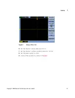
Set the oscilloscope Channel 1 probe attenuation to 1X.

c

Set the oscilloscope Channel 1 vertical sensitivity to 200 mV/div.

d

Set the oscilloscope horizontal sweep speed control to 5 ns/div.

e

Adjust the intensity to get a sharp, clear trace.

f

Adjust the oscilloscope’s trigger level so that the rising edge of the 

waveform at the center of the screen is located where the center horizontal 

and vertical grid lines cross (center screen).

g

Ensure the horizontal position control is set to 0.0 seconds.

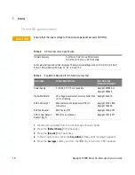
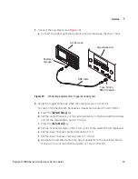
Figure 9

Connecting Equipment for Time Scale Accuracy Test

Oscilloscope

Signal Generator

BNC cable

Type-N (m) to

BNC (f) adapter

50

W

 feed

through

Summary of Contents for 1000B Series

Page 1: ...Keysight 1000B Series Oscilloscopes Service Guide ...

Page 2: ...escribed in this document are furnished under a license and may be used or copied only in accor dance with the terms of such license Restricted Rights Legend If software is for use in the performance of a U S Government prime contract or subcon tract Software is delivered and licensed as Commercial computer software as defined in DFAR 252 227 7014 June 1995 or as a commercial item as defined in FA...

Page 3: ...odes with adjustable sensitivity to filter noise and avoid false triggers Math function waveforms add subtract multiply FFT USB ports host and device for easy printing saving and sharing of waveforms setups screen BMP files and CSV data files Internal storage for 10 waveforms and 10 setups Special digital filter and waveform recorder Built in 6 digit hardware frequency counter Multi language 11 us...

Page 4: ...copes Service Guide In This Book This guide contains service information for the Keysight 1000B Series oscilloscopes 1 Service Describes oscilloscope maintanance performance testing and what to do if your oscilloscope requires service ...

Page 5: ...he Oscilloscope 12 Testing Performance 13 Before Testing Performance 14 To test DC gain accuracy 16 To test analog bandwidth maximum frequency 21 To test time scale accuracy 29 To test trigger sensitivity 32 Performance Test Record 35 Returning the Oscilloscope to Keysight for Service 38 Contacting Keysight 39 A Safety Notices 41 Warnings 41 Safety Symbols 42 Index 43 ...

Page 6: ...6 Keysight 1000B Series Oscilloscopes Service Guide Contents ...

Page 7: ... Menu Item 19 Figure 4 Connecting Equipment for Maximum Frequency Check Test 23 Figure 5 Channel 1 Vertical Scale Setting 24 Figure 6 Channel 1 Horizontal Scale Setting 24 Figure 7 Averages Menu Item 25 Figure 8 Signal Generator Waveform 26 Figure 9 Connecting Equipment for Time Scale Accuracy Test 30 Figure 10 Connecting Equipment for Trigger Sensitivity Test 33 ...

Page 8: ...8 Keysight 1000B Series Oscilloscopes Service Guide Figures ...

Page 9: ...le 6 Equipment Required for Analog Bandwidth Test 22 Table 7 Oscilloscope Models and Signal Generator Frequency 27 Table 8 Time Scale Accuracy Specification 29 Table 9 Equipment Required for Time Scale Accuracy Test 29 Table 10 Trigger Sensitivity Specification 32 Table 11 Equipment Required for Trigger Sensitivity Test 32 Table 12 Performance Test Information 35 Table 13 DC Gain Test 35 Table 14 ...

Page 10: ...10 Keysight 1000B Series Oscilloscopes Service Guide Tables ...

Page 11: ...ng the Oscilloscope 12 Testing Performance 13 Performance Test Record 35 Returning the Oscilloscope to Keysight for Service 38 Contacting Keysight 39 This chapter describes oscilloscope maintanance performance testing and what to do if your oscilloscope requires service ...

Page 12: ... 2 Clean the external surfaces of the instrument with a soft cloth dampened with a mixture of mild detergent and water 3 Make sure that the instrument is completely dry before reconnecting it to a power source CAUTION Do not use too much liquid in cleaning the oscilloscope Water can enter the oscilloscope s front panel damaging sensitive electronic components ...

Page 13: ...ace to record test results Test Order The tests in this section may be performed in any order desired However it is recommended to conduct the tests in the order presented in this manual as this represents an incremental approach to performance verification This may be useful if you are attempting to troubleshoot a suspected problem Test Equipment Lists of equipment needed to conduct each test are...

Page 14: ...r compatibility Keysight E4418B Power Sensor Analog Bandwidth 100 kHz to 1 GHz 3 accuracy Keysight 8482A Power Splitter Analog Bandwidth Outputs differ by 0 15 dB Keysight 11667B BNC Cable DC Gain Accuracy qty 2 Time Scale Accuracy Trigger Sensitivity 50Ω characteristic impedance BNC m connectors Keysight 8120 1840 Keysight 10503A BNC Tee Adapter DC Gain Accuracy BNC Tee m f f Keysight 1250 0781 B...

Page 15: ...y on the front panel 2 In the Utility menu press Self Cal 3 Follow the on screen instructions NOTE Let the oscilloscope warm up before testing The oscilloscope under test must be warmed up with the oscilloscope application running for at least 30 minutes prior to the start of any performance test ...

Page 16: ...o 5 mV div 4 0 full scale 10 mV div to 10 V div 3 0 full scale Full scale is defined as 8 vertical divisions The major scale settings are 2 mV 5 mV 10 mV 20 mV 50 mV 100 mV 200 mV 500 mV 1 V 2 V 5 V and 10 V Table 4 Equipment Required for DC Gain Accuracy Test Description Critical Specifications Recommended Model Part Numbers Power Supply 0 V to 35 V DC 10 mV resolution Keysight E3633A or Keysight...

Page 17: ...cilloscopes Service Guide 17 6 Set the channel 1 probe attenuation to 1X 7 Set the channel 1 vertical sensitivity value to 2 mV div 8 Set the power supply to 6 mV 9 Connect the equipment as shown in Figure 2 Figure 1 Averages Menu Item ...

Page 18: ...1 Service 10 Press Measure 11 Press the Voltage softkey 12 Turn the entry knob to select the Vavg measurement as shown below Oscilloscope Power Supply BNC tee Digital Multimeter BNC f to dual banana Figure 2 Connecting Equipment for DC Gain Accuracy Test ...

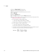
Page 19: ...negative power supply setting i Record the DMM voltage reading as VDMM ii Record the oscilloscope Vavg reading as VScope c Calculate the DC Gain using the following expression and record this value in the DC Gain Test section of the Performance Test Record 14 Repeat step 15 through step 23 for channel 2 15 Set the power supply voltage to 6 mV 16 Move the BNC cable from the previously tested channe...

Page 20: ...el s vertical sensitivities in the DC Gain Test section of the Performance Test Record on page 35 a For the positive power supply setting i Record the DMM voltage reading as VDMM ii Record the oscilloscope Vavg reading as VScope b For the negative power supply setting i Record the DMM voltage reading as VDMM ii Record the oscilloscope Vavg reading as VScope c Calculate the DC Gain using the follow...

Page 21: ...TION Ensure that the input voltage to the oscilloscope never exceeds 300 Vrms NOTE This procedure is the only acceptable method for testing the bandwidth of a 1000B Series oscilloscope Table 5 Analog Bandwidth Specification Analog Bandwidth 3 dB DSO1152B 150 MHz DSO1102B 100 MHz DSO1072B 70 MHz DSO1052B 50 MHz ...

Page 22: ...ysight 8648A Keysight E4400B or Keysight N5181A Power Meter Keysight E series with power sensor compatibility Keysight E4418B Power Sensor 100 kHz to 1 GHz 3 accuracy Keysight 8482A Power Splitter Outputs differ by 0 15 dB Keysight 11667B SMA Cable SMA m to SMA m 24 inch 50Ω BNC Feed Through Adapter 50Ω BNC f to BNC m feed through terminator Keysight 0960 0301 Type N to SMA Adapter Type N m to SMA...

Page 23: ...easurements in units of Watts 4 Press the Default Setup front panel key 5 Press the Auto Scale front panel key 6 Set the channel 1 probe attenuation to 1X 7 Set the channel 1 vertical scale to 200 mV div Oscilloscope Power Meter E4418B Power sensor cable Signal Generator Power splitter 11667B Type N m to SMA f adapter Power sensor 8482A SMA cable SMA to BNC adapter 50W feed through Figure 4 Connec...

Page 24: ...24 Keysight 1000B Series Oscilloscopes Service Guide 1 Service 8 Set the horizontal scale to 500 ns div Figure 5 Channel 1 Vertical Scale Setting Figure 6 Channel 1 Horizontal Scale Setting ...

Page 25: ...ppears 11 Press Average and turn the entry knob until 8 appears 12 Press Measure 13 Press the Voltage softkey 14 Turn the entry knob to select the Vpp menu item 15 Set the signal generator to a 1 MHz sine wave with a peak to peak amplitude of about 6 divisions as it appears on the oscilloscope screen Figure 7 Averages Menu Item ...

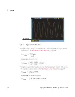
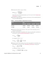
Page 26: ...e Test Record on page 35 For example if Vpp 1 20 V 17 Using the power meter reading convert this measurement to Volts RMS using the expression and record it in the Performance Test Record on page 35 For example if Pmeas 3 65 mW Figure 8 Signal Generator Waveform Vpp reading Vout1MHz Vpp1MHz 2 2 Vout1MHz 1 20 2 2 1 20 2 828 424 mV Vin1MHz Pmeas 50Ω Vin1MHz 3 65 mW 50Ω 427 mV ...

Page 27: ...ing calculate the Vrms value using the following expression and record it in the Performance Test Record on page 35 For example if Vpp 1 24 V 22 Using the power meter reading convert this measurement to Volts RMS using the expression and record it in the Performance Test Record on page 35 For example if Pmeas 3 65 mW Table 7 Oscilloscope Models and Signal Generator Frequency Setting Model DSO1152B...

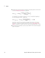
Page 28: ...uency 427 mV and Gain 1 MHz 0 993 then Record this value in the Calculated Gain Max Freq column in the Analog Bandwidth Maximum Frequency Check section of the Performance Test Record on page 35 To pass this test this value must be greater than 3 0 dB 24 For the remaining channels move the power splitter to the channel and repeat steps 4 through 23 Gain max 20 log10 Voutmax Vinmax Gain1MHz Gain Max...

Page 29: ...linearly from the oscilloscope s manufacture date and adds to the initial accuracy and temperature components 1 Set up the signal generator a Set the output to 10 MHz approximately 1 Vpp sine wave 2 Connect the output of the signal generator to oscilloscope channel 1 using the BNC cable Table 8 Time Scale Accuracy Specification Time Scale Accuracy 50 ppm over 1 ms Table 9 Equipment Required for Ti...

Page 30: ... speed control to 5 ns div e Adjust the intensity to get a sharp clear trace f Adjust the oscilloscope s trigger level so that the rising edge of the waveform at the center of the screen is located where the center horizontal and vertical grid lines cross center screen g Ensure the horizontal position control is set to 0 0 seconds Figure 9 Connecting Equipment for Time Scale Accuracy Test Oscillos...

Page 31: ...izontal sweep speed control to 10 ns div d Turn on the zoomed time base by pressing the Menu Zoom key followed by the Zoom softkey in the Horizontal menu e Record the number of nanoseconds from where the rising edge crosses the center horizontal grid line to the center vertical grid line The number of nanoseconds is equivalent to the time scale error in ppm f Record the result and compare it to th...

Page 32: ...div 1 div from DC to 10 MHz 1 5 div from 10 MHz to full bandwidth 5 mV div 1 div from DC to 10 MHz 1 5 div from 10 MHz to 20 MHz Table 11 Equipment Required for Trigger Sensitivity Test Description Critical Specifications Recommended Model Part Numbers Signal Generator 100 kHz to 1 GHz at 200 mVrms 0 01 Hz frequency resolution jitter 2 ps Keysight 8648A Keysight E4400B or Keysight N5181A BNC Cable...

Page 33: ... the signal generator to the bandwidth boundary and set the amplitude to about 10 mVpp c Press the Auto Scale key d Set the horizontal scale so that a few cycles of the waveform are displayed e Set the input channel s probe attenuation to 1X f Set the input channel s vertical scale to 5 mV div g Decrease the amplitude from the signal generator to the specified vertical division 1 5 div at maximum ...

Page 34: ...ut frequency of the signal generator to the bandwidth boundary and set the amplitude to about 10 mVpp c Press the Auto Scale key d Set the horizontal scale so that a few cycles of the waveform are displayed e Set the input channel s probe attenuation to 1X f Set the input channel s vertical scale to 2 mV div g Decrease the amplitude from the signal generator to the specified vertical division 1 5 ...

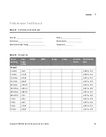
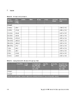
Page 35: ...___________________ Temperature ____________ Table 13 DC Gain Test Vertical Sensitivity Power Supply Setting VDMM VDMM VScope VScope Calculated DC Gain Offset Gain Test Limits Channel 1 2 mV div 6 mV 0 96 to 1 04 5 mV div 15 mV 0 96 to 1 04 10 mV div 30 mV 0 97 to 1 03 20 mV div 60 mV 0 97 to 1 03 50 mV div 150 mV 0 97 to 1 03 100 mV div 300 mV 0 97 to 1 03 200 mV div 600 mV 0 97 to 1 03 500 mV di...

Page 36: ...1 03 2 V div 6 0 V 0 97 to 1 03 5 V div 15 0 V 0 97 to 1 03 10 V div 30 0 V 0 97 to 1 03 Table 13 DC Gain Test continued Vertical Sensitivity Power Supply Setting VDMM VDMM VScope VScope Calculated DC Gain Offset Gain Test Limits Table 14 Analog Bandwidth Maximum Frequency Check Vin 1 MHz Vout 1 MHz Calculated Gain 1 MHz Test Limit greater than 3 dB Vin Max Freq Vout Max Freq Calculated Gain Max F...

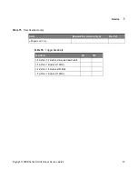
Page 37: ...15 Time Scale Accuracy Limits Measured time scale error ppm Pass Fail 50 ppm over 1 ms Table 16 Trigger Sensitivity Test Limits Ch1 Ch2 5 mV div 1 5 division at maximum bandwidth 5 mV div 1 division at 10 MHz 5 mV div 1 5 division at 20 MHz 5 mV div 1 division at 10 MHz ...

Page 38: ...ccessories from the oscilloscope Accessories include all cables Do not include accessories unless they are associated with the failure symptoms 3 Protect the oscilloscope by wrapping it in plastic or heavy paper 4 Pack the oscilloscope in foam or other shock absorbing material and place it in a strong shipping container You can use the original shipping materials or order materials from an Keysigh...

Page 39: ...Service 1 Keysight 1000B Series Oscilloscopes Service Guide 39 Contacting Keysight Information on contacting Keysight Technologies can be found at www keysight com find contactus ...

Page 40: ...40 Keysight 1000B Series Oscilloscopes Service Guide 1 Service ...

Page 41: ...ive conductor of the mains power cord The mains plug shall only be inserted in a socket outlet provided with a protective earth contact You must not negate the protective action by using an extension cord power cable without a protective conductor grounding Grounding one conductor of a two conductor outlet is not sufficient protection Only fuses with the required rated current voltage and specifie...

Page 42: ...the instrument may retain a charge even if the instrument is disconnected from its source of supply Do not operate the instrument in the presence of flammable gasses or fumes Operation of any electrical instrument in such an environment constitutes a definite safety hazard Do not use the instrument in a manner not specified by the manufacturer Safety Symbols Instruction manual symbol the product i...

Page 43: ...requency counter hardware 3 H hardware frequency counter 3 I input voltage 16 21 internal storage 3 L LED display 3 M math function waveforms 3 memory 3 22 model number 38 P performance test interval 13 performance test record 13 performance testing 13 R refresh rate 3 S safety notices 41 symbols 42 sample rate 3 serial number 38 symbols safety 42 T test equipment 13 testing performance 13 time me...

Page 44: ...44 Keysight 1000B Series Oscilloscopes Service Guide Index ...

Page 45: ......

Page 46: ... Keysight Technologies Inc 2012 2013 Printed in Available in electronic format only Third Edition April 2013 54139 97015 54139 97015 www keysight com ...

Reviews: