Interlock
Circuit
The
interlock
circuit
automatically
enables
interlocking
the
source
voltage
and
current
limit
function.
T
o
enable
this
function
in
your
custom
test
xture
,
the
16117C
provides
an
interlock
cable
.
This
section
describes
how
to
use
interlock
circuit
to
meet
your
custom
test
xture
requirements
.
Figure
3-3
shows
pin
assignments
for
the
interlock
cable
.
Figure
3-3.
Interlock
cable
Assignment
(Wiring
Side
View)
The
interlock
cable
has
six
lines
.
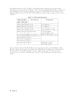
The
4339B
changes
some
settings:
V
oltage
Output,
Current
Limit,
and
Resistivity
Mode
,
depending
on
the
interlock
status
.
T
able
3-1,
describes
the
role
of
each
line:
T
able
3-1.
Pin
Assignment
of
Interlock
Connector
Pin
Name
Description
Interlock
Interrupt
signal
Disable
or
enable
V
oltage
Output
1
ID1
State
signal
2
Identicate
T
est
Fixture
ID2
ID3
Special
Signal
State
signal
used
for
16008B
switching
s
and
v
3
GND
Ground
Connected
to
Chassis
1
When
Interlock
line
is
grounded,
voltage
output
is
enabled.
2
Refer
to
T
able
3-2.
3
When
the
special
signal
line
is
grounded,
the
v
(RV )
mode
is
selected.
Operation
3-3
Summary of Contents for 16117C
Page 1: ...Keysight 16117C Low Noise Test Lead Operation and Service Manual...
Page 2: ......
Page 3: ......
Page 24: ......


