background image

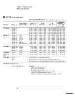
AC Characteristics

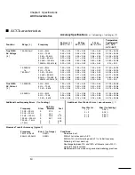
Measurement Noise Rejection


[ 8 ]  

AC CMRR

True RMS AC Voltage 


Measurement Method: 

Crest Factor:
AC Filter Bandwidth:

Slow 
Medium 
Fast

Input Impedance: 
Input Protection: 

True RMS AC Current


Measurement Method: 

Shunt Resistor: 
Burden Voltage:

Input Protection: 

70 dB

AC-coupled True RMS 

 measures

the ac component of input with up
to 400 Vdc of bias on any range.
Maximum 5:1 at full scale

3 Hz 

 300 kHz

20 Hz 

 300 kHz

200 Hz 

 300 kHz

1 M


±

 2%, in parallel with 100 pF

750 V rms all ranges

Direct coupled to the fuse and shunt.
AC-coupled True RMS measurement
(measures the ac component only).
0.1 

Ω 

 for 1 A and 3 A ranges

1 A range:  < 1 V rms
3 A range:  < 2 V rms
Externally accessible 3A, 250 V fuse
Internal 7A, 250 V fuse

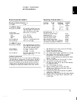
Settling Considerations


Applying >300 V rms (or >1 A rms) will cause self-heating in
signal-conditioning components. These errors are included in
the instrument specifications. Internal temperature changes
due to self-heating may cause additional error on lower ac
voltage ranges. The additional error will be less than 0.02%
of reading and will generally dissipate within a few minutes. 

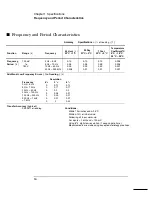
Measuring Characteristics

Function 

ACV, ACI 

 6

1

2


 6

1

2


 6

1

2


 6

1

2


 6

1

2


7 sec/reading

 1

   1.6 

[ 10 ]

    10 
    50 

[ 11 ]


AC Filter


Slow

Medium

Fast
Fast
Fast

System Speeds


[ 11 ]

 , 

[ 12 ]

Function or Range Change
Autorange Time
ASCII readings to RS-232
ASCII readings to GPIB
Max. Internal Trigger Rate
Max. External Trigger Rate to Memory
Max. External Trigger Rate to GPIB/RS-232

5/sec
<0.8 sec
50/sec
50/sec
50/sec
50/sec
50/sec

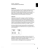
Operating Characteristics

  [ 9 ]

Reading/s

Digits

[ 1 ] 

  Specifications are for 1-hour warm-up at 6

1

2

 digits,

     Slow ac filter, sinewave input.  

[ 2 ]

    Relative to calibration standards.

[ 3 ]

    20% overrange on all ranges, except 750 Vac, 3 A range.

[ 4 ]

    Specifications are for sinewave input >5% of range. 

      For inputs from 1% to 5% of range and <50 kHz,
      add 0.1% of range additional error. For 50 kHz to 100 kHz,

  add 0.13% of range.

[ 5 ]

    750 Vac range limited to 100 kHz or 8x10

7

  Volt-Hz.

[ 6 ]

    Typically 30% of reading error at 1 MHz.

[ 7 ]

    For frequencies below 100 Hz, slow AC filter specified

 for sinewave input only. 

[ 8 ]

    For 1 k

 unbalance in LO lead.

[ 9 

]    Maximum reading rates for 0.01% of ac step 

 additional error. Additional settling delay required 

    when input dc level varies.

[ 10 ]

   For External Trigger or remote operation using default 

 settling delay ( Delay Auto ).

[ 11 ]

   Maximum useful limit with default settling delays defeated.

[ 12 ]

   Speeds are for 4

1

2

 digits, Delay 0, Display OFF, and 

 Fast AC filter.

1

Chapter 1  Specifications

15

Summary of Contents for 34401A

Page 1: ...Keysight 34401A 6 Digit Multimeter Service Guide ...

Page 2: ......

Page 3: ...ion contained herein Should Agilent and the user have a separate written agreement with warranty terms covering the material in this document that conflict with these terms the warranty terms in the separate agreement shall control Technology Licenses The hardware and or software described in this document are furnished under a license and may be used or copied only in accordance with the terms of...

Page 4: ...t lint free slightly dampened cloth Do not use detergent or chemical solvents Safety Symbols WARNING Main Power and Test Input Disconnect Unplug instrument from wall outlet remove power cord and remove all probes from all terminals before servicing Only qualified service trained personnel should remove the cover from the instrument WARNING Line and Current Protection Fuses For continued protection...

Page 5: ...Protection Limit The Protection Limit from HI to LO Input terminals is 1000 VDC or 750 VAC which is also the maximum voltage measurement This limit can also be expressed as 1000 Vpk maximum LO to Ground Protection Limit The LO input terminal can safely float a maximum of 500 Vpk relative to ground As is implied by the above limits the Protection Limit for the HI input terminal is a maximum of 1500...

Page 6: ...trical and Electronic Equipment WEEE Directive 2002 96 EC This product complies with the WEEE Directive 2002 96 EC marking requirement The affixed product label see below indicates that you must not discard this electrical electronic product in domestic household waste Product Category With reference to the equipment types in the WEEE directive Annex 1 this product is classified as a Monitoring an...

Page 7: ...1 1998 EN 61000 4 2 1995 IEC 61000 4 3 1995 EN 61000 4 3 1995 IEC 61000 4 4 1995 EN 61000 4 4 1995 IEC 61000 4 5 1995 EN 61000 4 5 1995 IEC 61000 4 6 1996 EN 61000 4 6 1996 IEC 61000 4 11 1994 EN 61000 4 11 1994 Canada ICES 001 1998 Australia New Zealand AS NZS 2064 1 Limit Group 1 Class A 4kV CD 8kV AD 3 V m 80 1000 MHz 0 5kV signal lines 1kV power lines 0 5 kV line line 1 kV line ground 3V 0 15 ...

Page 8: ...lt in math operations Continuity and diode test functions Hands free Reading Hold feature Portable ruggedized case with non skid feet Flexible System Features GPIB IEEE 488 interface and RS 232 interface Standard programming languages SCPI Agilent 3478A and Fluke 8840 Reading rates up to 1000 readings per second Storage for up to 512 readings Limit testing with pass fail signals Optional 34812A In...

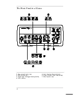
Page 9: ...a Glance 1 Measurement Function keys 2 Math Operation keys 3 Single Trigger Autotrigger Reading Hold key 4 Shift Local key 5 Front Rear Input Terminal Switch 6 Range Number of Digits Displayed keys 7 Menu Operation keys 2 ...

Page 10: ...en unless the multimeter is UNSECURED for calibration B MATH MENU 1 MIN MAX 2 NULL VALUE 3 dB REL 4 dBm REF R 5 LIMIT TEST 6 HIGH LIMIT 7 LOW LIMIT C TRIGger MENU 1 READ HOLD 2 TRIG DELAY 3 N SAMPLES D SYStem MENU 1 RDGS STORE 2 SAVED RDGS 3 ERROR 4 TEST 5 DISPLAY 6 BEEP 7 COMMA 8 REVISION E Input Output MENU 1 HP IB ADDR 2 INTERFACE 3 BAUD RATE 4 PARITY 5 LANGUAGE The menu is organized in a top d...

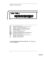
Page 11: ...al trigger Reading Hold is enabled Turns on when reading memory is enabled Multimeter is in dcv dcv ratio function A math operation is enabled null min max dB dBm or limit test Hardware or remote interface command errors are detected Rear input terminals are selected Shift key has been pressed Press Shift again to turn off Multimeter is in 4 wire ohms function Multimeter is in continuity test func...

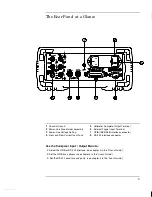
Page 12: ...lete Output Terminal 6 External Trigger Input Terminal 7 GPIB IEEE 488 Interface connector 8 RS 232 interface connector Use the front panel Input Output Menu to Select the GPIB or RS 232 interface see chapter 4 in the User s Guide Set the GPIB bus address see chapter 4 in the User s Guide Set the RS 232 baud rate and parity see chapter 4 in the User s Guide 5 ...

Page 13: ...nu examples Calibration Procedures Chapter 4 provides a detailed description of the multimeter s calibrations and adjustments Theory of Operation Chapter 5 describes each functional block in the multimeter Service Chapter 6 provides guidelines for returning your multimeter to Agilent for servicing or for servicing it yourself Replaceable Parts Chapter 7 contains a detailed parts list of the multim...

Page 14: ...Adjust the Carrying Handle 32 To Measure Voltage 33 To Measure Resistance 33 To Measure Current 34 To Measure Frequency or Period 34 To Test Continuity 35 To Check Diodes 35 To Select a Range 36 To Set the Resolution 37 To Make Null Relative Measurements 38 To Store Minimum and Maximum Readings 39 To Make dB Measurements 40 To Make dBm Measurements 41 To Trigger the Multimeter 42 To Make dcv dcv R...

Page 15: ...Security Code 73 Calibration Count 75 Calibration Message 75 Calibration Procedures 76 Aborting a Calibration in Progress 76 Zero Adjustment 77 Gain Adjustment 79 Optional Gain Calibration Procedures 82 Understanding the AC Signal Filter 85 Understanding Resolution 86 Error Messages 89 Chapter 5 Theory of Operation Block Diagram 93 Front Rear Selection 94 Function Switching 95 DC Amplifier 96 Ohms...

Page 16: ...n Assembly 127 Replaceable Parts 34401 66512 Display Assembly 133 Replaceable Parts Agilent 34401A Mainframe 134 Manufacturer s List 135 Chapter 8 Backdating 137 Chapter 9 Schematics Mechanical Disassembly 9 3 Component Locator Diagram Main Board 34401 66501 9 5 Component Locator Diagram Front Panel 34401 66512 9 6 Agilent 34401A Block Diagram 9 7 Front Rear Selection Schematic 9 8 Function Switch...

Page 17: ...Contents 10 ...

Page 18: ...1 Specifications 1 ...

Page 19: ... 001 0 010 0 001 0 010 0 001 0 040 0 001 0 800 0 010 0 0006 0 0005 0 0006 0 0001 0 0006 0 0001 0 0006 0 0001 0 0010 0 0002 0 0030 0 0004 0 1500 0 0002 DC Current 10 00000 mA 100 0000 mA 1 000000 A 3 000000 A 0 1 V 0 6 V 1 V 2 V 0 005 0 010 0 01 0 004 0 05 0 006 0 10 0 020 0 030 0 020 0 030 0 005 0 080 0 010 0 120 0 020 0 050 0 020 0 050 0 005 0 100 0 010 0 120 0 020 0 002 0 0020 0 002 0 0005 0 005...

Page 20: ...000 V on all ranges Selectable 4 wire or 2 wire ohms Current source referenced to LO input 10 of range per lead for 100 Ω 1 kΩ ranges 1 kΩ per lead on all other ranges 1000 V on all ranges 0 1Ω for 1A 3A 5Ω for 10 mA 100 mA Externally accessible 3A 250 V fuse Internal 7A 250 V fuse 300 samples sec with audible tone Adjustable from 1 Ω to 1000 Ω Input HI LO Reference HI LO 100 mV to 1000 V ranges 1...

Page 21: ...0 20 0 02 True RMS AC Current 4 1 000000 A 3 00000 A 3 Hz 5 Hz 5 Hz 10 Hz 10 Hz 5 kHz 3 Hz 5 Hz 5 Hz 10 Hz 10 Hz 5 kHz 1 00 0 04 0 30 0 04 0 10 0 04 1 10 0 06 0 35 0 06 0 15 0 06 1 00 0 04 0 30 0 04 0 10 0 04 1 10 0 06 0 35 0 06 0 15 0 06 1 00 0 04 0 30 0 04 0 10 0 04 1 10 0 06 0 35 0 06 0 15 0 06 0 100 0 006 0 035 0 006 0 015 0 006 0 100 0 006 0 035 0 006 0 015 0 006 Additional Low Frequency Erro...

Page 22: ...n ACV ACI 61 2 61 2 61 2 61 2 61 2 7 sec reading 1 1 6 10 10 50 11 AC Filter Slow Medium Fast Fast Fast System Speeds 11 12 Function or Range Change Autorange Time ASCII readings to RS 232 ASCII readings to GPIB Max Internal Trigger Rate Max External Trigger Rate to Memory Max ExternalTrigger Rate to GPIB RS 232 5 sec 0 8 sec 50 sec 50 sec 50 sec 50 sec 50 sec Operating Characteristics 9 Reading s...

Page 23: ...05 0 001 0 001 Additional Low Frequency Errors of reading 4 Frequency Resolution 61 2 51 2 41 2 0 0 12 0 12 0 0 17 0 17 0 0 2 0 2 0 0 06 0 21 0 0 03 0 21 0 0 01 0 07 0 0 0 02 3 Hz 5 Hz 5 Hz 10 Hz 10 Hz 40 Hz 40 Hz 100 Hz 100 Hz 300 Hz 300 Hz 1 kHz 1 kHz Transfer Accuracy typical 0 0005 of reading Conditions Within 10 minutes and 0 5 C Within 10 of initial value Following a 2 hour warm up For input...

Page 24: ...when measuring low voltage low frequency signals Shielding inputs from external noise pickup is critical for minimizing measurement errors Measuring Characteristics Function Frequency Period 61 2 51 2 41 2 1 9 8 80 System Speeds 5 Configuration Rates Autorange Time ASCII readings to RS 232 ASCII readings to GPIB Max Internal Trigger Rate Max External Trigger Rate to Memory Max ExternalTrigger Rate...

Page 25: ...lligator and grabber attachments User s Guide Service Guide test report and power cord Triggering and Memory Reading HOLD Sensitivity Samples per Trigger Trigger Delay External Trigger Delay External Trigger Jitter Memory 0 01 0 1 1 or 10 of reading 1 to 50 000 0 to 3600 sec 10 µs step size 1 ms 500 µs 512 readings Math Functions Null Min Max Average dB dBm Limit Test with TTL output dBm reference...

Page 26: ...Product Dimensions Product Dimensions 348 3 mm 88 5 mm 212 6 mm 261 1 mm 379 4 mm 103 8 mm TOP Product Dimensions All dimensions are shown in millimeters 1 Chapter 1 Specifications 19 ...

Page 27: ...ification pages If you are operating the multimeter outside the 23 C 5 C temperature range specified apply an additional temperature coefficient error For dc voltage dc current and resistance measurements you may need to apply an additional reading speed error or autozero OFF error For ac voltage and ac current measurements you may need to apply an additional low frequency error or crest factor er...

Page 28: ... or a ppm part per million of input error as shown below of input error Total Measurement Error Input Signal Level 100 ppm of input error Total Measurement Error Input Signal Level 1 000 000 Error Example Assume that a 5 Vdc signal is input to the multimeter on the 10 Vdc range Compute the total measurement error using the 90 day accuracy specifications 0 0020 of reading 0 0005 of range Range 10 V...

Page 29: ... to a 61 2 digit measurement with 20 overrange capability Sensitivity Sensitivity is the minimum level that the multimeter can detect for a given measurement Sensitivity defines the ability of the multimeter to respond to small changes in the input level For example suppose you are monitoring a 1 mVdc signal and you want to adjust the level to within 1 µV To be able to respond to an adjustment thi...

Page 30: ...National Institute of Standards and Technology To be meaningful the accuracy specifications must be accompanied with the conditions under which they are valid These conditions should include temperature humidity and time There is no standard convention among multimeter manufacturers for the confidence limits at which specifications are set The table below shows the probability of non conformance f...

Page 31: ...specified for a 24 hour period and for a 1 C temperature range 90 Day and 1 Year Accuracy These long term accuracy specifications are valid for a 23 C 5 C temperature range These specifications include the initial calibration errors plus the multimeter s long term drift errors Temperature Coefficients Accuracy is usually specified for a 23 C 5 C temperature range This is a common temperature range...

Page 32: ...urther noise reduction Set the input resistance to greater than 10 GΩ for the 100 mV 1 V and 10 V ranges for the best dc voltage accuracy Use 4 wire ohms for the best resistance accuracy Use Math Null to null the test lead resistance for 2 wire ohms and to remove interconnection offset for dc voltage measurements AC Voltage and AC Current Measurements Set the resolution to 6 digits Select the slow...

Page 33: ...26 ...

Page 34: ...2 Quick Start 2 ...

Page 35: ...arious functions and operations Most keys have a shifted function printed in blue above the key To perform a shifted function press Shift the Shift annunciator will turn on Then press the key that has the desired label above it For example to select the dc current function press Shift DC V If you accidentally press Shift just press it again to turn off the Shift annunciator The rear cover of this ...

Page 36: ... on self test The GPIB bus address is displayed Notice that the multimeter powers up in the dc voltage function with autoranging enabled To review the power on display with all annunciators turned on hold down Shift as you turn on the multimeter 3 Perform a complete self test The complete self test performs a more extensive series of tests than those performed at power on Hold down Shift as you pr...

Page 37: ...timeter into is energized 2 Verify the power line voltage setting The line voltage is set to the proper value for your country when the multimeter is shipped from the factory Change the voltage setting if it is not correct The settings are 100 120 220 or 240 Vac for 230 Vac operation use the 220 Vac setting See the next page if you need to change the line voltage setting 3 Verify that the power li...

Page 38: ...mbly from the rear panel 2 Remove the line voltage selector from the assembly 3 Rotate the line voltage selector until the correct voltage appears in the window 4 Replace the fuse holder assembly in the rear panel Verify that the correct line voltage is selected and the power line fuse is good 2 Chapter 2 Quick Start If the Multimeter Does Not Turn On 31 ...

Page 39: ...Handle To adjust the position grasp the handle by the sides and pull outward Then rotate the handle to the desired position Bench top viewing positions Carrying position Chapter 2 Quick Start To Adjust the Carrying Handle 32 ...

Page 40: ...1000 V 750 Vac Maximum resolution 100 nV on 100 mV range AC technique true RMS ac coupled To Measure Resistance Ranges 100 Ω 1 kΩ 10 kΩ 100 kΩ 1 MΩ 10 MΩ 100 MΩ Maximum resolution 100 µΩ on 100 ohm range 2 Chapter 2 Quick Start To Measure Voltage 33 ...

Page 41: ...imum resolution 10 nA on 10 mA range AC technique true RMS ac coupled To Measure Frequency or Period Measurement band 3 Hz to 300 kHz 0 33 sec to 3 3 µsec Input signal range 100 mVac to 750 Vac Technique reciprocal counting Chapter 2 Quick Start To Measure Current 34 ...

Page 42: ... fixed at 1 kohm Beeper threshold 1 Ω to 1000 Ω beeps below adjustable threshold To Check Diodes Test current source 1 mA Maximum resolution 100 µV range is fixed at 1 Vdc Beeper threshold 0 3 volts Vmeasured 0 8 volts not adjustable 2 Chapter 2 Quick Start To Test Continuity 35 ...

Page 43: ...he front panel ranging applies to the signal s input voltage not its frequency The range is fixed for continuity 1 kΩ range and diode 1 Vdc range Ranging is local to the selected function This means that you can select the ranging method auto or manual for each function independently When manually ranging the selected range is local to the function the multimeter remembers the range when you switc...

Page 44: ...he resolution is fixed at 51 2 digits for continuity and diode tests You can also vary the number of digits displayed using the arrow keys however the integration time is not changed Resolution is local to the selected function This means that you can select the resolution for each function independently The multimeter remembers the resolution when you switch between functions Press the Shift key ...

Page 45: ...ading taken after you press Null is stored as the null value in the Null Register Any previously stored value is replaced with the new value After enabling null you can edit the stored null value by pressing Shift Menu Recall This takes you to the NULL VALUE command in the MATH MENU only if null is enabled Go down to the parameter level and then edit the displayed value The null register is cleare...

Page 46: ...This takes you to the MIN MAX command in the MATH MENU only if min max is enabled Go down to the parameter level and then read the values by pressing or The stored values are cleared when you turn min max off turn off the power or perform a remote interface reset The average is of all readings taken since min max was enabled not just the average of the stored minimum and maximum The count is the t...

Page 47: ... is replaced with the new value After enabling dB operations you can edit the relative value by pressing Shift Menu Recall This takes you to the dB REL command in the MATH MENU only if dB is enabled Go down to the parameter level and then edit the value displayed The register is cleared when you change functions turn dB off turn off the power or perform a remote interface reset Enables dB operatio...

Page 48: ...to the dBm REF R command in the MATH MENU only if dBm is enabled Go down to the parameter level and then select a value 50 75 93 110 124 125 135 150 250 300 500 600 800 900 1000 1200 or 8000 ohms The reference resistance is stored in non volatile memory and does not change when power has been off or after a remote interface reset Enables dBm operation Press again to disable Math annunciator is on ...

Page 49: ... an External Trigger The external trigger mode is also enabled by pressing It is like the single trigger mode except that you apply a trigger pulse to the rear panel Ext Trig terminal The multimeter is triggered on the negative edge of a TTL pulse The front panel key is disabled when in remote Single Single Enables single trigger and triggers the multimeter Trig annunciator is on when the multimet...

Page 50: ... reference voltage measurements on the Sense terminals The Input LO and Sense LO terminals must have a common reference and cannot have a voltage difference greater than 2 volts The specified measurement range applies only to the signal connected to the Input terminals The signal on the Input terminals can be any dc voltage up to 1000 volts Ratio dc signal voltage dc referencevoltage Ratio annunci...

Page 51: ...dc range 41 2 digits are displayed 113 325 6 OHM This is the 100 ohm range 61 2 digits are displayed OVL D mVDC This is an overload indication on the 100 mVdc range 1 2 digit 5 digits Negative sign or blank positive H 1 2 digit 0 or 1 D Numeric digits E Exponent m k M F Measurement units VDC OHM HZ dB 1 2 digit Chapter 2 Quick Start Front Panel Display Formats 44 ...

Page 52: ...ny Agilent System II instrument of the same size can be rack mounted beside the 34401A Remove the carrying handle and the front and rear rubber bumpers before rack mounting the multimeter To remove the handle rotate it to the vertical position and pull the ends outward Front Rear bottom view To remove the rubber bumper stretch a corner and then slide it off 2 Chapter 2 Quick Start To Rack Mount th...

Page 53: ...nts side by side order lock link kit 5061 9694 and flange kit 5063 9212 To install one or two instruments in a sliding support shelf order shelf 5063 9255 and slide kit 1494 0015 for a single instrument also order filler panel 5002 3999 Chapter 2 Quick Start To Rack Mount the Multimeter 46 ...

Page 54: ...3 Menu Tutorial 3 ...

Page 55: ...f measurements If you are not familiar with this information we recommend that you read chapter 2 Quick Start starting on page 27 This chapter introduces you to the front panel menu It describes each menu and takes you step by step through calibration examples See chapter 3 Features and Functions in the User s Guide for a complete discussion of the multimeter s capabilities and operation 48 ...

Page 56: ...null register Recalls or sets the dBm value stored in the dB relative register Selects the dBm reference resistance value Enables or disables limit testing Sets the upper limit for limit testing Sets the lower limit for limit testing 1 READ HOLD 2 TRIG DELAY 3 N SAMPLES Sets the reading hold sensitivity band Specifies a time interval which is inserted before a measurement Sets the number of sample...

Page 57: ...eration Selects the interface language SCPI Agilent 3478 or Fluke 8840 42 1 SECURED 1 UNSECURED 2 CALIBRATE 3 CAL COUNT 4 MESSAGE The multimeter is secured against calibration enter code to unsecure The multimeter is unsecured for calibration enter code to secure Performs complete calibration of present function must be UNSECURED Reads the total number of times the multimeter has been calibrated R...

Page 58: ...ameters You move down or up the menu tree to get from one level to the next Each of the three levels has several horizontal choices which you can view by moving left or right To turn on the menu press Shift Menu On Off To turn off the menu press Shift Menu On Off or press any of the function or math keys on the top row of front panel keys To execute a menu command press Enter To recall the last me...

Page 59: ...s displayed after you press Menu Enter to execute the command MIN VALUE The value you specified on the parameter level is too small for the selected command The minimum value allowed is displayed for you to edit MAX VALUE The value you specified on the parameter level is too large for the selected command The maximum value allowed is displayed for you to edit EXITING MENU You will see this message...

Page 60: ...hoice on this level A MEAS MENU 2 Move across to the CAL MENU choice on this level There are six menu group choices available on the menus level Each choice has a letter prefix for easy identification A B etc F CAL MENU 3 Move down to the commands level within the CAL MENU Either SECURED or UNSECURED is the first command on this level If SECURED is displayed you must unsecure the multimeter so tha...

Page 61: ... code from its factory setting you can unsecure the multimeter by entering 034401 from the front panel Only the last six characters are recognized from the front panel and they must be numeric characters only 034401 CODE We recommend that you use a unique SECURE code for each multimeter to obtain the maximum benefit from the electronic calibration security features of the multimeter To secure the ...

Page 62: ...ompleting this example will perform a zero calibration Refer to chapter 4 Calibration Procedures before attempting this example 1 Turn on the menu You enter the menu on the menus level The MEAS MENU is your first choice on this level A MEAS MENU 2 Move across to the CAL MENU choice on this level There are six menu group choices available on the menus level Each choice has a letter prefix for easy ...

Page 63: ...r prefix for easy identification 1 2 etc 2 CALIBRATE 5 Move down to edit the CALIBRATE VALUE parameter The calibration value should read 100 000 0 mVDC when you come to this point in the menu for the first time when set to 100 mVdc range For this example you will set the calibration value to 0 0 volts 100 000 0 mVDC When you see the flashing on the left side of the display you can abort the edit a...

Page 64: ...tor of 10 Notice that the position of the decimal point changes and the displayed number increases by a factor of 10 0 000 000 VDC 10 Save the change and turn off the menu The multimeter beeps and displays a message to show that the change is now in effect You are then exited from the menu The zero offset calibration procedure determines new calibration constants for each function and range Separa...

Page 65: ...58 ...

Page 66: ...4 Calibration Procedures 4 ...

Page 67: ...lter 85 Understanding Resolution 86 Error Messages 89 The performance verification tests use the multimeter s specifications listed in chapter 1 Specifications starting on page 11 Closed Case Electronic Calibration The multimeter features closed case electronic calibration since there are no internal mechanical adjustments required The multimeter automatically prompts you for the required full sca...

Page 68: ...tervals beyond 2 years for any application Whatever calibration interval you select Agilent recommends that complete re adjustment should always be performed at the calibration interval This will increase your confidence that the Agilent 34401A will remain within specification for the next calibration interval This criteria for re adjustment provides the best measure of the multimeter s long term ...

Page 69: ... Fluke calibration commands You must use the SCPI calibration commands described in chapter 4 of the Agilent 34401A User s Guide You can also adjust the multimeter from the remote interface Remote adjustment is similar to the local front panel procedure You can use a computer to perform the adjustment by first selecting the required function and range The calibration value is sent to the multimete...

Page 70: ...t value measured from the source can be entered into the 34401A Multimeter as the target calibration value Application Zero Calibration DC Voltage DC Current Resistance AC Voltage AC Current Frequency Recommended Equipment None Fluke 5700A Fluke 5700A 5725A Fluke 5700A Fluke 5700A 5725A Fluke 5700A 5725A Agilent 3325A Accuracy Requirements 4 terminal short using ONLY copper interconnections 1 5 dm...

Page 71: ... only copper connections to minimize thermal offset voltages Use shielded twisted PTFE â insulated cable to minimize high resistance errors Keep cables as short as possible Allow 5 minutes after handling input connections for thermal offset voltage settling Because the multimeter is capable of making highly accurate measurements you must take special care to ensure that the calibration standards a...

Page 72: ...ey as you press the Power switch to turn on the multimeter hold down the key for more than 5 seconds a complete description of these tests can be found in chapter 6 The multimeter meter will automatically perform the complete self test procedure when you release the key The self test will complete in approximately 20 seconds You can perform many tests individually or all tests at once using the TE...

Page 73: ...ollowing Perform a complete self test Perform only the performance verification tests indicated with the letter Q If the multimeter fails the quick performance check adjustment or repair is required Performance Verification Tests The performance verification tests are recommended as acceptance tests when you first receive the multimeter The acceptance test results should be compared against the 90...

Page 74: ...nfiguration 61 2 digit slow or fast resolution MEAS MENU 1 Make sure you have read Test Considerations on page 64 2 Apply a 4 wire short copper across the Input HI LO and Sense HI LO terminals as shown below front or rear terminal 3 Select the shorted terminal set front or rear with the front rear switch Separate zero offset calibration constants are stored for the front and rear input terminals 4...

Page 75: ...Short Short Short DC Current DC Volts 2 Wire Ohms 1 and 4 Wire Ohms Q Q Q 10 mA 100 mA 1 A 3 A 100 mV 1 V 10 V 100 V 1000 V 100 Ω 1 kΩ 10 kΩ 100 kΩ 1 MΩ 10 MΩ 100 MΩ 1 µA 4 µA 60 µA 600 µA 3 µV 6 µV 40 µV 600 µV 6 mV 3 mΩ 5 mΩ 50 mΩ 500 mΩ 10 Ω 100 Ω 10 kΩ 2 µA 5 µA 100 µA 600 µA 3 5 µV 7 µV 50 µV 600 µV 10 mV 4 mΩ 10 mΩ 100 mΩ 1 Ω 10 Ω 100 Ω 10 kΩ 2 µA 5 µA 100 µA 600 µA 3 5 µV 7 µV 50 µV 600 µV ...

Page 76: ...year 100 mV 1 V 10 V 10 V 100 V 1000 V 100 Ω 1 kΩ 10 kΩ 100 kΩ 2 1 MΩ 2 10 MΩ 2 100 MΩ 2 10 mA 100 mA 1 A 2 A DC Volts 2 Wire Ohms 1 and 4 Wire Ohms DC Current Q Q Q Q Q 100 mV 1 V 10 V 10 V 100 V 1000 V 100 Ω 1 kΩ 10 kΩ 100 kΩ 1 MΩ 10 MΩ 100 MΩ 10 mA 100 mA 1 A 3 A 6 µV 26 µV 190 µV 190 µV 2 6 mV 26 mV 6 mΩ 25 mΩ 250 mΩ 2 5 Ω 30 Ω 1 6 kΩ 310 kΩ 1 5 µA 14 µA 560 µA 2 6 mA 7 5 µV 37 µV 250 µV 250 µ...

Page 77: ...r 90 day 1 year 10 mV 100 mV 100 mV 1 V 1 V 10 V 10 V 10 V 100 V 100 V 750 V 750 V 1 1 kHz 1 kHz 50 kHz 1 kHz 50 kHz 1 kHz 50 kHz 10 Hz 1 kHz 50 kHz 1 kHz 50 kHz Q Q Q 100 mV 100 mV 1 V 10 V 100 V 750 V 34 µV 70 µV 150 µV 600 µV 1 4 mV 6 mV 14 mV 6 mV 60 mV 140 mV 450 mV 1 05 V 45 µV 90 µV 160 µV 800 µV 1 6 mV 8 mV 16 mV 8 mV 80 mV 160 mV 600 mV 1 2 V 46 µV 100 µV 170 µV 900 µV 1 7 mV 9 mV 17 mV 9...

Page 78: ... on page 64 2 Select each function and range in the order shown below Compare measurement results to the appropriate test limits shown in the table Be certain to allow for appropriate source settling Input Front Input Frequency 34401A Range Error From Nominal 24 hour 90 day 1 year 1A 2A 1 kHz 1 kHz 1A 3A 1 4 mA 4 8 mA 1 4 mA 4 8 mA 1 4 mA 4 8 mA Input Front Input Frequency Quick Check 34401A Range...

Page 79: ... in the order shown below Compare measurement results to the appropriate test limits shown in the table Be certain to allow for appropriate source settling Input Front Input Frequency 34401A Range Error From Nominal 24 hour 90 day 1 year 1 V 1 V 1 V 1 V 1 V 1 V 10 V 1 V 100 mV 20 Hz 1 kHz 20 kHz 50 kHz 100 kHz 300 kHz 1 kHz 1 kHz 1 kHz 1 V 1 V 1 V 1 V 1 V 1 V 10 V 10 V 10 V 600 µV 600 µV 600 µV 1 ...

Page 80: ...r must be a letter but the remaining characters can be letters or numbers You do not have to use all 12 characters but the first character must always be a letter A _ _ _ _ _ _ _ _ _ _ _ 12 characters To secure the multimeter from the remote interface so that it can be unsecured from the front panel use the eight character format shown below The first two characters must be HP and the remaining ch...

Page 81: ...ical disassembly drawing on page 9 3 3 Remove the internal metal shields push the top shield to the side and then lift out see the mechanical disassembly drawing on page 9 3 4 Connect the power cord and turn on the multimeter Be careful not to touch the power line connections 5 Apply a short between the two exposed metal pads on JM500 located between U500 and U506 The exposed metal pads are outlin...

Page 82: ...is no way provided to program or reset the calibration count It is an independent electronic calibration serialization value Calibration Message You can use the calibration message feature to record calibration information about your multimeter For example you can store such information as the last calibration date the next calibration due date the multimeter s serial number or even the name and p...

Page 83: ...Gain Adjustment Procedure Perform the Verification Tests Secure the multimeter Note the new secure code and calibration count in your maintenance records for future reference Aborting a Calibration in Progress Sometimes it may be necessary to abort a calibration after the procedure has already been initiated You can abort a calibration at any time by pressing any front panel key except Shift When ...

Page 84: ...re is intended to save calibration time and improve zero calibration consistency Caution Never turn off the multimeter during Zero Adjustment This may cause ALL calibration memory to be lost Zero Adjustment Procedure The automatic zero adjustment procedure takes about 5 minutes to complete for each terminal set calibrated front or rear terminal Follow the steps outlined below Review Test Considera...

Page 85: ...ect F CAL MENU 4 Use to move down to the commands level and select 2 CALIBRATE 5 Use to move down to the parameters level and then set the input value to 000 0000 mV 6 Execute the command by pressing Auto Man 7 Perform the Zero Offset Verification tests see page 67 to check zero calibration results 8 Repeat steps 1 through 7 for the other input terminal set front or rear terminal ENTER Chapter 4 C...

Page 86: ...r the tables used for gain adjustments Gain Adjustment Considerations The zero adjustment procedure must have been recently performed prior to beginning any gain adjustment procedures The optional 10 Vdc 500 Vdc and 10 mA calibrations should be performed only after servicing the multimeter s a to d converter or after replacing network U101 or calibration RAM U505 Refer to the Optional Gain Calibra...

Page 87: ...ation table see pages 69 through 71 2 Apply the input signal shown in the Input column of the appropriate verification table Always complete tests in the same order as shown in the appropriate verification table Function Range Valid Calibration Input Values DC V Ω 2W Ω 4W DC I AC V 1 Frequency 100 mV to 100 V 1000 V 100 Ω to 10 MΩ 10 mA to 1 A 3 A 10 mV to 100 V 750 V Any 0 9 to 1 1 x Full Scale 9...

Page 88: ...ration value for the present input value 6 Execute the command by pressing Auto Man 7 Perform the appropriate Gain Verification Test to check the calibration results 8 Repeat steps 1 through 7 for each gain verification test point shown in the tables Each range in the gain adjustment procedure takes less than 20 seconds to complete ENTER 4 Chapter 4 Calibration Procedures Gain Adjustment 81 ...

Page 89: ...ustment should ONLY be performed after servicing the a to d converter or replacement of the calibration RAM U505 Configuration DC volts 61 2 digit slow resolution NPLC 100 MEAS MENU 1 Perform the 10 V dc gain adjustment procedure Note the multimeter s reading immediately following the 10 V calibration 2 Manually reverse the multimeter s input connections and allow time for thermal offset voltages ...

Page 90: ...e this procedure correctly will generate error 725 500V DC correction out of range Configuration DC volts 1000 V range 61 2 digit slow or fast resolution MEAS MENU 1 Perform the complete dc Volts gain calibration procedure 2 Apply 500 Vdc to the input terminals 3 Enter the CALibration MENU as shown in steps 3 through 6 of the Gain Adjustment Procedure section on page 80 Enter the exact known value...

Page 91: ... procedure A failure to complete this procedure correctly will generate error 736 AC rms 100th scale linearity correction out of range Configuration AC current 1 A range 61 2 digit slow or fast resolution MEAS MENU AC FILTER slow MEAS MENU 1 Perform the complete ac volts gain calibration procedure 2 Apply 10 mA 1 kHz ac to the current input terminals 3 Enter the CALibration MENU as shown in steps ...

Page 92: ...peration Select from the menu the slow filter 3 Hz medium filter 20 Hz or fast filter 200 Hz The default is the medium filter 1 AC FILTER MEAS MENU Remote Interface Operation Specify the lowest frequency expected in the input signal The multimeter selects the appropriate filter based on the frequency you specify see table above The CONFigure and MEASure commands select the 20 Hz filter DETector BA...

Page 93: ...pondence between the number of digits selected and the resulting integration time in power line cycles is shown below The autozero mode is set indirectly when you set the resolution Resolution is local to the selected function This means that you can select the resolution for each function independently The multimeter remembers the resolution when you switch between functions Resolution Choices Fa...

Page 94: ...changing the number of digits does more than just change the resolution of the multimeter It also changes the integration time which is the period the multimeter s analog to digital A D converter samples the input signal for a measurement For ac measurements the resolution is actually fixed at 61 2 digits If you select 41 2 digits or 51 2 digits the multimeter masks one or two digits The only way ...

Page 95: ...n not in number of digits For example for dc volts specify the resolution in volts For frequency specify the resolution in hertz CONF VOLT DC 10 0 001 41 2 digits on the 10 Vdc range MEAS CURR AC 1 1E 6 61 2 digits on the 1 A range CONF FREQ 1 KHZ 0 1 Hz 1000 Hz input 0 1 Hz resolution VOLT AC RES 0 05 50 mV resolution on the ac function CONFigure function range MIN MAX DEF resolution MIN MAX DEF ...

Page 96: ...3 604 605 606 607 608 609 610 611 612 613 614 615 616 617 618 619 620 621 622 623 624 625 626 Front panel does not respond RAM read write failed A D sync stuck A D slope convergence failed Cannot calibrate rundown gain Rundown gain out of range Rundown too noisy Serial configuration readback failed DC gain x1 failed DC gain x10 failed DC gain x100 failed Ohms 500 nA source failed Ohms 5 uA source ...

Page 97: ...ence failed AC low frequency convergence failed AC low frequency correction out of range AC rms converter noise correction out of range AC rms 100th scale linearity correction out of range Cal checksum failed secure state Cal checksum failed string data Cal checksum failed DCV corrections Cal checksum failed DCI corrections Cal checksum failed RES corrections Cal checksum failed FRES corrections C...

Page 98: ...5 Theory of Operation 5 ...

Page 99: ...his chapter followed by more detailed descriptions of the circuitry contained in the schematics chapter Block Diagram 93 Front Rear Selection 94 Function Switching 95 DC Amplifier 96 Ohms Current Source 98 AC Circuit 99 A to D Converter 101 Floating Logic 103 Earth Referenced Logic 105 Power Supplies 106 Front Panel 107 The self test procedures are described in chapter 6 92 ...

Page 100: ...ng Data stored at the time of calibration is recalled and used to correct the measurement data The corrected reading is then formatted and sent to the front panel processor for display The corrected reading can also be sent to the earth referenced I O processor for output to the remote interface The earth referenced circuitry consists of a processor configured as a slave to the main CPU This proce...

Page 101: ... The double fused F101 F102 current input is designed to protect against potential catastrophic damage caused by accidental input connection across high VA sources beyond the 250 V rating of the rear panel current input fuse U110 bootstraps out the offset current errors caused by the leakage current of CR100 CR100 clamps the current input to protect R120 and R121 from excessive overloads Caution O...

Page 102: ...from U150 Function K101 K102 K103 K104 Sense at 0 1 V 10 Vdc 100 V 1000 Vdc 2 Wire Ohms 4 Wire Ohms AC Voltage Frequency Period 3 A 1A DC I 100 mA 10 mA DC I 3A 1A AC I Closed Closed Closed Closed Closed Closed Closed Closed Closed Set Set Reset Reset Set Set Reset Set Reset Set Reset Set Set Reset Reset Set Set Set Set 1 Set Reset 2 Reset 2 Reset Reset Reset Reset Set U101 5 U102 12 U101 5 3 AC_I...

Page 103: ... off 1 In the dc voltage function ranging is accomplished through both input relay switching K101 K104 and solid state switching U101 As a result the input to the ADC has the same nominal 10V value for a full scale input on each range The dc input op amp is comprised of source follower dual FET U104 amplifier U106 and associated bias circuitry The feedback resistors U102C and switches U101C select...

Page 104: ...al 10 MΩ resistance is determined whenever a zero calibration is performed In the 2 wire ohms function the voltage drop is measured across the Input HI and Input LO terminals In the 4 wire ohms function the voltage is measured across the HI Sense and LO Sense terminals Lead resistances in series with the current source Input HI LO are not part of the final measurement However they do reduce the av...

Page 105: ...sistor 5 kΩ 50 kΩ 500 kΩ 1 MΩ by U201B The resulting precision current flows through JFET Q202 and protection circuit Q203 to Q211 and CR202 to relay K102 where it is switched to the Input HI terminal for ohms measurements The protection circuits are designed to protect the ohms current source from inadvertently applied voltages in excess of 1000 V Protection from large positive voltages is provid...

Page 106: ... contain a dc bias from the applied ac signal Input coupling capacitor C301 blocks the dc portion of the input signal Only the ac component of the input signal is measured by the multimeter The ac circuit voltage ranging comprises two gain stages U301 and U305 U312 The voltage gains for each stage are tabulated below The 1st stage is a compensated attenuator implementing a gain of x0 2 or x0 002 a...

Page 107: ... offset from the amplifier stages is blocked by capacitor C316 Buffer U307 drives the input to the rms to dc converter as well as the frequency comparator U310A input The rms to dc converter has two selectable averaging filters C318 and C318 plus C321 for the analog computer circuit of U308 The two analog averaging filters together with digital filters running in the main CPU implement the three s...

Page 108: ...acitor to cancel or balance the accumulated input charge The level shifted R403 and R406 output of the integrator is checked every 2 66 µs by the U501 COMP input Logic state machines in U501 control the U411 current steering to continuously seek an approximate 2 5 V level on the integrator amplifier output FLASH If the ADC input voltage ADIN is between 15 V the integrator output FLASH will remain ...

Page 109: ...00 The instrument precision voltage reference is U403 Resistor R409 provides a stable bias current for the reference zener diode R408 and CR404 provide a bias to assure that the reference zener biases to 7 V during power up IC U400A amplifies the voltage reference to 10 V while amplifier U401A inverts the 10 V reference to 10 V The reference voltages force precision slope currents for the integrat...

Page 110: ...external ROM and RAM When the address latch enable ALE signal goes high address data is present on the address data bus Custom gate array U501 latches the address data and decodes the correct chip enable low true for external ROM and RAM accesses and for read write accesses to the internal registers of U501 The system memory map is shown below Program ROM U502 contains four 64k x 8 banks of data B...

Page 111: ...erial data is clocked out The measurement configuration readback data SERRBK is only checked during self test operation Front panel data is exchanged in both directions whenever a byte is sent from U501 The measurement configuration register data is strobed to outputs by U500 signal SERSTB Interrupts from the front panel are detected by U501 and signaled to the processor by CHINT The processor lin...

Page 112: ...sent in an 11 bit frame at a rate of 187 5 k bits second When the RS 232 interface is selected data is sent across the isolated link at 93 75 k bits second The 11 bit data frame is configured for one start bit eight data bits one control bit and one stop bit Earth Referenced Logic The earth referenced logic circuits schematic shown on page 9 14 provide all rear panel input output capability Microp...

Page 113: ...n the unregulated dc input to the regulator falls below 5 5 volts XPONRST is the instrument master hardware reset signal This supply powers all floating logic Relay drive circuits are also powered from this supply The floating 18 volt supplies are produced by bridge rectifier CR551 filter capacitors C551 and C553 and regulators U551 and U552 These supplies are used to power all measuring circuits ...

Page 114: ...front panel logic low supply 13 volts is produced by the 18 volt supply and 4 7 V zener CR606 Level shift outputs for the front panel receive data are clamped to the 13 volt supply VLB Display anode and grid voltages are 18 volts for an on segment and 18 volts for an off segment The 12 V cathode bias for the display is provided by filament winding center tap bias circuit CR556 R556 and C559 on the...

Page 115: ...108 ...

Page 116: ...6 Service 6 ...

Page 117: ...lude the following Operating Checklist 111 Types of Service Available 112 Repackaging for Shipment 113 Electrostatic Discharge ESD Precautions 114 Surface Mount Repair 114 To Replace the Power Line Fuse 114 To Replace the Current Input Fuses 115 To Connect the Pass Fail Output Signals 115 Troubleshooting Hints 117 Self Test Procedures 120 110 ...

Page 118: ...lected See To Prepare the Multimeter for Use on page 29 Remove all measurement connections to the multimeter Ensure that all measurement terminal connections both front and rear terminals are removed while the self test is performed Errors may be induced by ac signals present on the multimeter input terminals during self test Long test leads can act as an antenna causing pick up of ac signals Is t...

Page 119: ...TYPES OF SERVICE AVAILABLE For details of service call Solid Signal at 877 312 4547 Chapter 6 Service Types of Service Available 112 ...

Page 120: ...ng label will be supplied Agilent will notify you when your failed unit has been received If the instrument is to be shipped to Agilent for service or repair be sure to Attach a tag to the multimeter identifying the owner and indicating the required service or repair Include the instrument model number and full serial number Place the multimeter in its original container with appropriate packaging...

Page 121: ...c styrofoam vinyl paper and other static generating materials from the immediate work area Use only anti static solder suckers Surface Mount Repair Surface mount components should only be removed using soldering irons or desoldering stations expressly designed for surface mount components Use of conventional solder removal equipment will almost always result in permanent damage to the printed circ...

Page 122: ...the multimeter s rear panel is a 9 pin connector DB 9 male connector When the RS 232 interface is not selected IEEE 488 interface is selected the internal pass and fail TTL output signals limit testing may be connected to the RS 232 connector The pass and fail signals are low true and indicate the Math Pass Fail Limit Test result for the next reading to be output to the GPIB interface The signals ...

Page 123: ...assembly drawing on page 9 3 4 Install JM710 and JM711 located adjacent to the power supply connector P751 A bare wire may be used if a 0 ohm surface mount resistor is not available See the component locator diagram for the 34401 66501 Main PC Board on page 9 5 5 Reassemble the multimeter Make sure to reinstall the bottom cover screw Do not use the RS 232 interface if you have configured the multi...

Page 124: ...r Verify that the front panel Power switch is depressed Verify that the power line fuse is good Verify the power line voltage setting See To Prepare the Multimeter for Use on page 29 Unit reports an error between 740 and 748 These errors may be produced if you accidentally turn off power to the unit during a calibration or while changing a non volatile state of the instrument Recalibration or rese...

Page 125: ...e reference U403 will cause many self test failures Be certain that U403 is seated properly in its socket Check the main supply voltages as shown below Readings indicate OVERLOAD An overload is caused when the gain and offset corrected reading result is greater than the full scale value or less than the full scale value for the present measuring function and range This can be caused by incorrect c...

Page 126: ...asuring ranges to show more noise than the least sensitive ranges Verify that the multimeter fails to meet its zero input specifications Low frequency ac measurements will experience more noise than higher frequency inputs Verify that the multimeter fails to meet ac specifications Ensure that the correct ac filter is selected for the applied input signal frequency If calibration constants become c...

Page 127: ...l U600 Self test 603 checks that the ADC logic is functioning U501 Self test 604 checks that the ADC analog hardware is functioning Self test 626 checks that U700 passed its self test Self Test Descriptions This section provides a brief description for each internal self test procedure including purpose test setup and failure criteria Erroneous self test failures may occur when the power line volt...

Page 128: ... writes and reads a 55H and AAH checker board pattern to each address of ram U503 Any incorrect readback will cause a test failure This error is only readable from the remote interface 603 A D sync stuck The main CPU issues an A D sync pulse to U500 38 and to U501 where ADC slope counters are latched A failure is detected when a sync interrupt is not recognized and a subsequent time out occurs 604...

Page 129: ...rmed and checked against a limit of 0 6 V 0 3 V 611 DC gain x100 failed This test configures for the 100 mV dc range The dc amplifier gain is set to x100 The measure customer MC input is selected to the internal TSENSE source which produces 0 6 volts A 20 ms ADC measurement is performed and checked for a overload response 612 Ohms 500 nA source failed This test configures to the 10 V dc range with...

Page 130: ...hecked against a limit of 7 5 V 3 V 618 DC high voltage attenuator failed This test configures to the 1000 V dc range The 500 nA ohms current source is connected to produce a nominal 5 V signal A 20 ms ADC measurement is performed and the result is checked against a limit of 5 V 1 V 619 Ohms 1 mA source failed This test configures to the 10 V dc range with the internal 10 M 100 1 divider U102A con...

Page 131: ...ading is taken in the PRE state The precharge amplifier voltage offset is calculated The U500 DAC output is set to about 1 5 volts and the precharge offset is measured again The gain of the offset adjustment is calculated This test assures a precharge amplifier offset adjustment is achievable 624 Unable to sense line frequency This test checks that the LSENSE logic input to U500 is toggling If no ...

Page 132: ...7 Replaceable Parts 7 ...

Page 133: ...ber and manufacturer part number To Order Replaceable Parts You can order replaceable parts from Agilent using the Agilent part number or directly from the manufacturer using the manufacturer s part number Note that not all parts listed in this chapter are available as field replaceable parts To order replaceable parts from Agilent do the following 1 Contact your nearest Agilent Sales Office or Se...

Page 134: ... 50 V 04222 08051A6R8DAT A C305 0160 6096 1 Capacitor Fxd 470 pF 5 50 V 04222 12061A471JAT A C306 0160 5972 1 Capacitor Fxd 5 6 pF 8 93 50 V 04222 08051A5R6DAT A C307 0160 5967 Capacitor Fxd 100 pF 5 50 V 04222 08051A101JAT A C308 C310 0160 6497 Capacitor Fxd 0 1 uF 10 50 V 04222 12065C104KAT A C311 C312 0180 4116 6 Capacitor Fxd 22 uF 20 20 V 28480 0180 4116 C313 0160 5955 1 Capacitor Fxd 68 pF 5...

Page 135: ... Diode Full Wave Bridge 100V 4A 71744 KBU4B CR103 1902 1565 3 Diode Zener 4 7V 5 TO 236 28480 1902 1565 CR201 1902 1565 Diode Zener 4 7V 5 TO 236 28480 1902 1565 CR202 1901 1378 1 Diode HV Rectifier 1 6KV 500 mA 71744 GP10Y CR203 1902 1592 Diode Zener 5 1V 5 TO 236 28480 1902 1565 CR302 CR303 1906 0291 10 Diode Dual 70V 100 mA TO 236AA 04713 MBAV99 CR304 CR307 1902 1541 6 Diode Zener 3 3V 5 TO 236...

Page 136: ...ype 3 Contact 27264 26 64 4030 PCB1 34401 26501 1 Printed Circuit Board Blank 28480 34401 26501 Q104 1855 0752 2 Transistor J FET N Chan D Mode 27014 MMBF4392 Q150 Q153 1854 1014 4 Transistor NPN SI PD 350 mW Ft 100MHz 04713 MMBT6429 Q201 1855 0752 Transistor J FET N Chan D Mode 27014 MMBF4392 Q202 1855 0863 1 Transistor J FET P Chan D Mode 27014 MMBF5461SEL Q203 Q210 1853 0727 8 Transistor PNP SI...

Page 137: ...699 1423 Resistor 215 1 125W 28480 0699 1423 R309 0699 1329 Resistor 6 19K 1 125W 28480 0699 1329 R310 0699 1360 1 Resistor 46 4 1 125W 28480 0699 1360 R311 R312 0699 1412 3 Resistor 75K 1 125W 28480 0699 1412 R313 0699 1329 Resistor 6 19K 1 125W 28480 0699 1329 R314 0699 1398 Resistor 21 5K 1 125W 28480 0699 1398 R315 0699 1327 Resistor 1M 1 125W 28480 0699 1327 R316 0699 1423 Resistor 215 1 125W...

Page 138: ...55 0699 1406 1 Resistor 42 2K 1 125W 28480 0699 1406 R556 0699 1391 Resistor 10K 1 125W 28480 0699 1391 R701 0699 3408 1 Resistor 1K 5 1W 91637 CRCW2512 102J R702 0699 1398 Resistor 21 5K 1 125W 28480 0699 1398 R703 0699 1391 Resistor 10K 1 125W 28480 0699 1391 R704 0699 1330 Resistor 100K 1 125W 28480 0699 1330 R705 0699 1318 Resistor 1K 1 125W 28480 0699 1318 R706 0699 3407 1 Resistor 100 5 1W 9...

Page 139: ...0 1820 1479 1 IC MCU Embedded 80C196 PLCC68S 34649 N80C196KB U501 1820 8907 1 IC Gate Array CMOS 27014 SCX6206AK0 U502 34401 88806 1 Prog EPROM 1818 5680 28480 34401 88806 See above 1818 5680 1 IC 2M BIT OTP ROM 120 ns CMOS 04078 M27C2001 12C1E U503 1818 4777 1 IC CMOS 262144 256K STAT RAM 70 ns 28480 1818 4777 U505 1818 5236 1 IC 4K EEPROM 500 ns CMOS2 7014N M93C66M8 U506 1990 1552 2 Opto Isolato...

Page 140: ...7 MCR18 F X 1002 R605 R608 0699 1423 4 Resistor 215 1 125W TKF TC 0 100 2M627 MCR18 F X 2150 R609 R610 0699 1391 Resistor 10K 1 125W TKF TC 0 100 2M627 MCR18 F X 1002 R611 R612 0699 1330 2 Resistor 100K 1 125W TKF TC 0 100 2M627 MCR18 F X 1003 R613 0699 1399 Resistor 23 7K 1 2M627 MCR18 F X 2372 R614 R617 0699 1344 4 Resistor 10 1 125W TKF TC 0 100 2M627 MCR18 F X 10R0 R618 0699 1378 1 Resistor 2 ...

Page 141: ...01 MP11 MP12 34401 86020 2 Bumpers Front Rear Power Mod Cvr 28480 34401 86020 SCW1 SCW8 0515 0433 8 Screw M4 X 0 7 8mm Lg Pan Hd 28480 0515 0433 SHD1 34401 00603 1 Shield Top 28480 34401 00603 SHD2 34401 00602 1 Shield Bottom 28480 34401 00602 T901 9100 4972 1 Transformer Power 28480 9100 4972 Exchange Unit 34401 69211 1 Rebuilt 34401A Unit for Exchange 28480 34401 69211 For serial numbers prior t...

Page 142: ... Corp Sunnyvale CA U S A 94086 24226 Gowanda Electronics Corp Gowanda NY U S A 14070 24355 Analog Devices Inc Norwood MA U S A 02062 27014 National Semiconductor Corp Santa Clara CA U S A 95052 27264 Molex Inc Lisle IL U S A 60532 28480 Agilent Technologies Inc Palo Alto CA U S A 94304 34335 Advanced Micro Devices Inc Sunnyvale CA U S A 94086 34649 INTEL Corp Santa Clara CA U S A 95054 50088 SGS T...

Page 143: ...136 ...

Page 144: ...8 Backdating 8 ...

Page 145: ... 5967 0160 5847 0160 5847 0160 5954 0699 1503 0699 1398 0699 1319 0699 1360 0699 1348 34401 67901 1820 6721 34401 88823 34401 88821 34401 8881 Part Description IC PRGMD Programmed EPROM Display PC Assembly Display PC Assembly Capacitor 01uF 1kV IC PRGMD Programmed EPROM Programmed EPROM Resistor 5 62K 1 Diode Zener 4 7V Crystal Quartz 12 0 MHz Shield ESD Shield ESD Capacitor Fxd 100 pF 5 Capacitor...

Page 146: ...ESD 28480 33120 00611 PCB1 34401 26502 1 Printed Circuit Board Blank 28480 34401 26502 R600 0699 1322 1 Resistor 68 1K 1 125W 28480 0699 1322 R602 0699 1378 1 Resistor 2 61K 1 125W 28480 0699 1378 R603 0699 1399 1 Resistor 23 7K 1 125W 28480 0699 1399 R604 0699 1398 1 Resistor 21 5K 1 125W 28480 0699 1398 R605 R606 0699 1330 6 Resistor 100K 1 125W 28480 0699 1330 R609 R611 0699 1396 3 Resistor 17 ...

Page 147: ...34401 66522 Display Assembly Component Locator Chapter 8 Backdating Agilent 34401A Multimeter 140 ...

Page 148: ...34401 66502 Schematic 141 Fold Here Fold Here Fold Here Fold Here ᑷ Binder Edge RH Page Foldout Cut Size 9 x 19 inches ᑷ Binder Edge RH Page Foldout Cut Size 9 x 19 inches ...

Page 149: ...9 Schematics 9 ...

Page 150: ...6 Agilent 34401A Block Diagram 9 7 Front Rear Selection Schematic 9 8 Function Switching Schematic 9 9 DC Amplifier and Ohms Schematic 9 10 AC Circuit Schematic 9 11 A D Converter Schematic 9 12 Floating Logic Schematic 9 13 Earth Referenced Logic Schematic 9 14 Power Supplies Schematic 9 15 Front Panel Display and Keyboard Schematic 9 16 9 2 ...

Page 151: ...Mechanical Disassembly 9 3 Fold Here Fold Here Fold Here Fold Here ಧ Binder Edge RH Page Foldout Cut Size 9 x 19 inches ಧ Binder Edge RH Page Foldout Cut Size 9 x 19 inches ...

Page 152: ...Mechanical Disassembly 9 4 Fold Here Fold Here Binder Edge LH Page ႐ Foldout Cut Size 9 x 19 inches Fold Here Fold Here Binder Edge LH Page ႐ Foldout Cut Size 9 x 19 inches ...

Page 153: ...Component Locator Diagram Main PC Board 34401 66501 9 5 Fold Here Fold Here Fold Here Fold Here ಧ Binder Edge RH Page Foldout Cut Size 9 x 19 inches ಧ Binder Edge RH Page Foldout Cut Size 9 x 19 inches ...

Page 154: ...ponent Locator Diagram Front Panel PC Board 34401 66512 9 6 Fold Here Fold Here Binder Edge LH Page ႐ Foldout Cut Size 9 x 19 inches Fold Here Fold Here Binder Edge LH Page ႐ Foldout Cut Size 9 x 19 inches ...

Page 155: ...Agilent 34401A Block Diagram 9 7 Fold Here Fold Here Fold Here Fold Here ಧ Binder Edge RH Page Foldout Cut Size 9 x 19 inches ಧ Binder Edge RH Page Foldout Cut Size 9 x 19 inches ...

Page 156: ...401 66501 sheet 1 of 8 Front Rear Selection Schematic 9 8 Fold Here Fold Here Binder Edge LH Page ႐ Foldout Cut Size 9 x 19 inches Fold Here Fold Here Binder Edge LH Page ႐ Foldout Cut Size 9 x 19 inches ...

Page 157: ...4401 66501 sheet 2 of 8 Function Switching Schematic 9 9 Fold Here Fold Here Fold Here Fold Here ಧ Binder Edge RH Page Foldout Cut Size 9 x 19 inches ಧ Binder Edge RH Page Foldout Cut Size 9 x 19 inches ...

Page 158: ...01 66501 sheet 3 of 8 DC Amplifier and Ohms Schematic 9 10 Fold Here Fold Here Binder Edge LH Page ႐ Foldout Cut Size 9 x 19 inches Fold Here Fold Here Binder Edge LH Page ႐ Foldout Cut Size 9 x 19 inches ...

Page 159: ...34401 66501 sheet 4 of 8 AC Circuit Schematic 9 11 Fold Here Fold Here Fold Here Fold Here ಧ Binder Edge RH Page Foldout Cut Size 9 x 19 inches ಧ Binder Edge RH Page Foldout Cut Size 9 x 19 inches ...

Page 160: ...34401 66501 sheet 5 of 8 A D Converter Schematic 9 12 Fold Here Fold Here Binder Edge LH Page ႐ Foldout Cut Size 9 x 19 in Fold Here Fold Here Binder Edge LH Page ႐ Foldout Cut Size 9 x 19 inc ...

Page 161: ...34401 66501 sheet 6 of 8 Floating Logic Schematic 9 13 Fold Here Fold Here Fold Here Fold Here ಧ Binder Edge RH Page Foldout Cut Size 9 x 19 inches ಧ Binder Edge RH Page Foldout Cut Size 9 x 19 inches ...

Page 162: ...01 66501 sheet 7 of 8 Earth Referenced Logic Schematic 9 14 Fold Here Fold Here Binder Edge LH Page ႐ Foldout Cut Size 9 x 19 inches Fold Here Fold Here Binder Edge LH Page ႐ Foldout Cut Size 9 x 19 inches ...

Page 163: ...34401 66501 sheet 8 of 8 Power Supplies Schematic 9 15 Fold Here Fold Here Fold Here Fold Here ಧ Binder Edge RH Page Foldout Cut Size 9 x 19 inches ಧ Binder Edge RH Page Foldout Cut Size 9 x 19 inches ...

Page 164: ...401 66512 sheet 1 of 1 Display and Keyboard Schematic 9 16 Fold Here Fold Here Binder Edge LH Page ႐ Foldout Cut Size 9 x 19 inches Fold Here Fold Here Binder Edge LH Page ႐ Foldout Cut Size 9 x 19 inches ...

Page 165: ...This information is subject to change without notice Keysight Technologies 1991 2014 Edition 9 August 2014 34401 90013 ...

Reviews: