Noise Rejection
Rejecting Power–Line Noise Voltages
A desirable characteristic of integrating analog–to–digital (A/D) converters is their ability to reject power–
line related noise present with DC input signals. This is called normal mode noise rejection, or NMR. The
multimeter achieves NMR by measuring the average DC input by "integrating" it over a fixed period. If you
set the integration time to a whole number of power line cycles (PLCs), these errors (and their harmonics)
will average out to approximately zero.
The multimeter provides three integration selections (1, 10, and 100 PLCs) that achieve NMR. The mul-
timeter measures the power–line frequency (50 Hz or 60 Hz), and then determines the corresponding
integration time. For a complete listing of NMR, approximate added rms noise, reading rate, and res-
olution for each integration setting, see the Performance vs. Integration Time table.
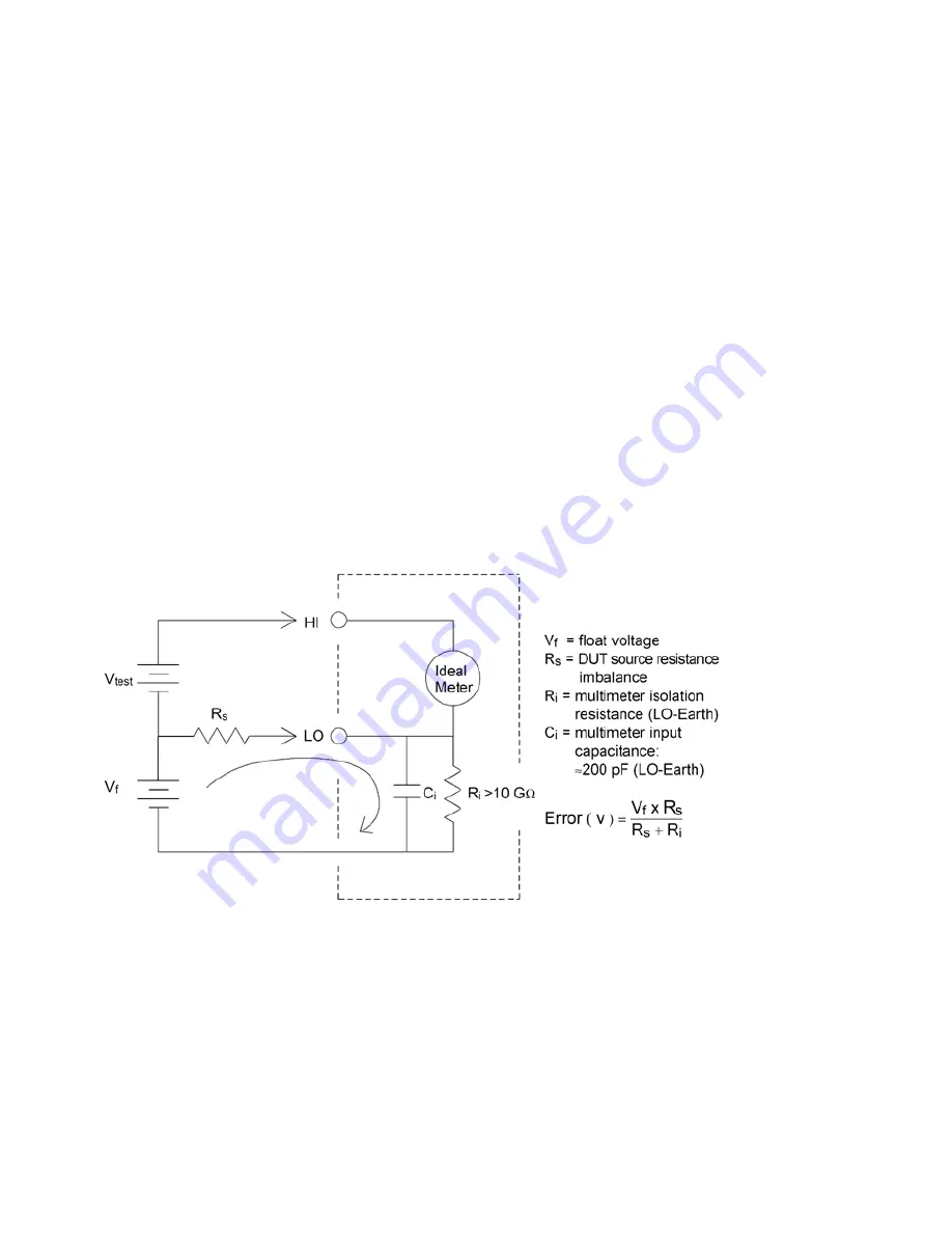
Common Mode Rejection (CMR)
Ideally, a multimeter is completely isolated from earth–referenced circuits. However, there is finite res-
istance between the multimeter's input LO terminal and earth ground, as shown below. This can cause
errors when measuring low voltages which are floating relative to earth ground.
Noise Caused by Magnetic Loops
When making measurements near magnetic fields, avoid inducing voltages in the measurement con-
nections. You should be especially careful when working near conductors carrying large currents. Use twis-
ted–pair connections to the multimeter to reduce the noise pickup loop area, or dress the test leads as
close together as possible. Loose or vibrating test leads will also induce error voltages. Tie down test leads
securely when operating near magnetic fields. Whenever possible, use magnetic shielding materials or
increased distance from magnetic sources.
Keysight True
volt
Series Operating and Service Guide
163
Measurement Tutorial


