background image

2

Base Matrix Configuration

144

Keysight 34934A User’s Guide

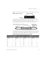
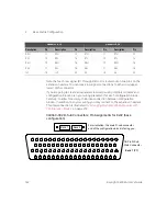
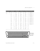
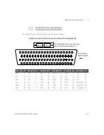
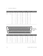
34934C-001 D-Sub Connectors: Wiring for 8x32

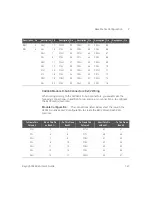
Safety Interlock Continuity 

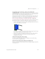
While wiring to the 34934C-002’s D-Sub 

connectors, you 

must

 make the following connections—in addition to the 8x32 

row and column connections—to provide for safety interlock continuity:

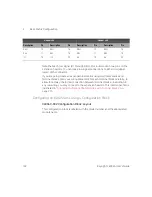
Description Pin

Description Pin

Description Pin

Description Pin

Description Pin

Description Pin

R1H

1

No connect 7

No connect 25

No connect 45

No connect 64

IL1

61

R1L

2

No connect 8

No connect 26

No connect 46

No connect 65

IL2

40

R2H

5

No connect 9

No connect 27

No connect 47

No connect 66

Com Gnd

60

R2L

6

No connect 10

No connect 28

No connect 48

No connect 67

R3H

41

No  connect 11

No  connect 29

No  connect 49

No  connect 68

R3L

42

No  connect 12

No  connect 30

No  connect 50

No  connect 69

R4H

43

No  connect 13

No  connect 31

No  connect 51

No  connect 70

R4L

44

No  connect 14

No  connect 32

No  connect 52

No  connect 71

R5H

23

No  connect 15

No  connect 33

No  connect 53

No  connect 72

R5L

24

No  connect 16

No  connect 34

No  connect 54

No  connect 73

R6H

3

No connect 17

No connect 35

No connect 55

No connect 74

R6L

4

No connect 18

No connect 36

No connect 56

No connect 75

R7H

62

No  connect 19

No  connect 37

No  connect 57

No  connect 76

R7L

63

No  connect 20

No  connect 38

No  connect 58

No  connect 77

R8H

21

No connect 39

No connect 59

No connect 78

R8L

22

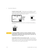
NOTE

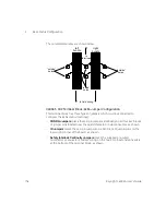
The D-Sub connector pin assignments for the 34934C-001 configuration block 

mirror those shown for the 34934A module. However—for safety reasons—

the 

D-Sub pin assignments for the 34934C-002 configuration block 

do not

 mirror 

those for the 34934A module.

 Please consult the correct configuration sections


for wiring to the D-Sub connectors.

Summary of Contents for 34934A

Page 1: ...Keysight 34934A High Density Matrix Module User s Guide...

Page 2: ...vernment rights in excess of these rights customarily provided to the public to use modify reproduce release perform display or disclose commercial computer software or commercial computer software do...

Page 3: ...ons which must be taken to maintain safe operation of the instrument Alternating current AC Frame or chassis ground terminal Standby supply Unit is not completely disconnected from ac mains when switc...

Page 4: ...e impaired if it is used in a manner not specified in the operation instructions Before Applying Power Verify that all safety precautions are taken Make all connections to the unit before applying pow...

Page 5: ...he instrument cover Do Not Modify the Instrument Do not install substitute parts or perform any unauthorized modification to the product Return the product to an Keysight Sales and Service Office for...

Page 6: ...itoring and Control Instrument product The affixed product label is as shown below Do not dispose in domestic household waste To return this unwanted instrument contact your nearest Keysight Service C...

Page 7: ...s and Technical Support 6 1 Overview of the 34934A 34934A High Density Matrix Module 12 Operating Considerations 13 General Configuration Procedures for the 34934A 16 Benefits of Using the Terminal an...

Page 8: ...by Direct Wiring 145 8x64 Matrix Configuration 150 Configuring an 8x64 Matrix using a Terminal Block 151 Configuring an 8x64 Matrix using a Configuration Block 160 Configuring an 8x64 Matrix by Direc...

Page 9: ...ommand Summary 229 Opening and Closing Channels 230 Querying Channels for Open or Closed State 231 Querying the Mainframe for Module Identity 232 Setting the Relay Protection Mode 232 Reading Relay Cy...

Page 10: ...10 Keysight 34934A User s Guide THIS PAGE HAS BEEN INTENTIONALLY LEFT BLANK...

Page 11: ...12 Practical Examples for Selecting a Matrix Configuration Mode 23 This chapter provides an overview of the 34934A High Density Matrix Module It includes operating and general configuration informati...

Page 12: ...our independent matrices or as two independent 2 wire matrices As dual 4x64 matrices MH ML You can operate these as two independent matrices or as a single 2 wire matrix As a single 4x128 matrix As du...

Page 13: ...ontinuity at the D Sub connectors are provided for each configuration If you connect your field wiring using the optional terminal blocks or configuration blocks available from Keysight you must also...

Page 14: ...and ABUS4 are for signal routing only and do not connect to the DMM You can connect from a row column crosspoint directly to the external 9 pin Analog Bus connector located on the 34980A s rear panel...

Page 15: ...00 In this mode closing any channel also closes the Row Protection Relay for that row placing a 100 resistor in the signal path from that channel s 32 column bank see above The Row Protection Relay re...

Page 16: ...in open until the row protection mode is changed the instrument is reset or power is cycled to the instrument This operation is independent of the state open closed of any channel relays See Setting t...

Page 17: ...ub connectors c Connect your field wiring to the configuration block 5 If using direct wiring a Connect your field wiring to the module s D Sub connectors using the corresponding D Sub connector drawi...

Page 18: ...ix using the base configuration instructions in Chapter 2 4 Create a daisy chain connection between the modules either by interconnecting the terminal blocks or configuration blocks using the instruct...

Page 19: ...terminals and or extension headers 100V J24 J25 JUMPERS ID CONFIG JUMPERS FOR 4X128 AND 4X32 USE OVERLAY 34934T OPT001 1W 2W MIXED 1W OPERATION DUAL H L 4X64 ID JUMPERS UNUSED 1 0 2W OPERATION 4X64 C...

Page 20: ...or extension headers In addition you will have to short two pins on each D Sub to provide safety interlock continuity All other configuration is done within the block this saves significant wiring ti...

Page 21: ...Browser Interface with the 34934A The 34980A Web Browser interface accessible by PC via a LAN connection is highly useful for helping you visualize the 34934A matrix topologies nomenclature and channe...

Page 22: ...eans to control the module the Web Browser offers the easiest method to view the channel map for any set configuration of the module For complete guidance on LAN connection and navigating the 34980A W...

Page 23: ...ix Physical location of the Row Protection Resistors relative to the rows and columns Row jumpers used to create the matrix from its 4 row by 32 column elemental components The row jumper represents t...

Page 24: ...oceed to the section of Chapter 2 which provides configuration and wiring instructions for the chosen base matrix 4x32 Matrices 4x32 Topology You can select the 4x32 matrix configuration by setting ju...

Page 25: ...your test devices between corresponding high and low matrix terminals or D Sub pins then operate the matrix in 2 wire mode by using SCPI paired commands e g ROUT OPEN PAIR A potential application of t...

Page 26: ...Operation Test Circuit Examples The two examples below each show a 2 wire circuit path One path uses matrix 1 left side of the 34934T 001 terminal block the other path uses matrix 2 right side of term...

Page 27: ...C32H M1H M1L C1H C32H 1303 1533 1563 M2H M2L C1L C32L C1L C32L 1302 INST DUT DUT INST ROUT CLOS PAIR 1302 1303 Paired channels are 1366 1367 ROUT CLOS PAIR 1533 1563 Paired channels are 1597 1627 1366...

Page 28: ...s then operate the matrix in 2 wire mode by using SCPI paired commands e g ROUT OPEN PAIR In either mode of operation each matrix MH ML is created by jumpering the rows on two of the 4x32 relay banks...

Page 29: ...DUT and instrument connected to columns but through two resistors On ML The upper example path connects the DUT to an instrument on row R1 both crosspoints are on the same 32 relay bank without the in...

Page 30: ...e complete circuit includes four 100 series Row Protection Resistors with Bypass Relays As with any path which makes a row connection or which C1H C32H MH C33H C64H R3H R1H R2H R4H ML C1L C32L C33L C6...

Page 31: ...r the row protection resistor and bypass relay MH ML C1L C32L C33L C64L INST DUT 1503 1535 1567 1599 ROUT CLOS PAIR 1503 1535 Paired channels are 1567 1599 row R3H columns C3H and C35H row R3L columns...

Page 32: ...ables The row jumpers are shown on the example Each bank connects to the next through one 100 Row Protection Resistor with Bypass Relay per row The examples which follow show multiple ways to connect...

Page 33: ...3 DUT INST C65 C96 1366 INST C97 C128 1599 1397 DUT DUT ROUT CLOS 1502 1599 Closes Row R3 columns C2 and C99 Path 1 ROUT CLOS 1133 1164 Closes Row R1 columns C33 and C64 Path 2 ROUT CLOS 1366 1397 Clo...

Page 34: ...w matrix terminals or D Sub pins then operate the matrix in 2 wire mode by using SCPI paired commands e g ROUT OPEN PAIR In either mode of operation each matrix MH ML is created by jumpering the colum...

Page 35: ...ST INST 1564 1534 1233 1263 ROUT CLOS 1801 1402 1432 row R8H column C1H row R4H columns C2H and C34H ROUT CLOS 1233 1263 1534 1564 row R2L columns C1L and C33L row R5L columns C2L and C34L R3H R1H R2H...

Page 36: ...e SCPI paired commands ROUTe CLOSe PAIR To close two crosspoints in 2 wire operation you specify two H crosspoints the paired command also closes the two L crosspoints C1H C32H ML C1L C32L INST DUT MH...

Page 37: ...not The row jumpers connect a bank to paired bank through one 100 Row Protection Resistor with Bypass Relay per row The example which follows show two ways to connect your DUT and test instrument eac...

Page 38: ...C1 C32 C33 C64 INST DUT 1831 1232 1234 INST DUT R8 R8 R7 R7 R6 R6 R5 R5 R4 R4 R3 R3 R2 R2 R1 R1 R3 R1 R2 R4 R7 R5 R6 R8 ROUT CLOS 1831 1232 1234 row R8 column C31 row R2 columns C32 and C34 Closes Se...

Page 39: ...ns between your D Sub cables The column jumpers are not indicated in the example On the 34934T 002 terminal block there are redundant sets of terminals provided for columns 1 32 one set on each side o...

Page 40: ...User s Guide C1 C32 INST INST DUT DUT 1581 1551 1752 R3 R1 R2 R4 R7 R5 R6 R8 R11 R9 R10 R12 R15 R13 R14 R16 ROUT CLOS 1551 1581 1752 row R10 columns C1 and C31 row R14 column C2 Closes See Channel Num...

Page 41: ...x32 Matrix Configuration 122 8x64 Matrix Configuration 150 16x32 Matrix Configuration 178 This chapter contains six independent sections Each contains complete configuration and wiring instructions fo...

Page 42: ...Block 4x32 Wiring on page 49 Configuration Block You can use configuration block 34934C 001 Follow these sections in order to configure and wire the configuration block 34934C 001 Configuration Block...

Page 43: ...ock 4x32 Layout This terminal block with screw type connections is labeled with the model number and the abbreviated module name In addition space is available on the label for you to write the slot n...

Page 44: ...L H L H L H L C 5 C 7 C 8 C 9 R 3 R 4 C 9 C 10 C 11 C 12 C 13 C 14 H L H L H L H L H L H L C 15 C 16 C 17 C 18 C 19 C 20 C 21 C 22 C 23 C 24 C 25 C 26 H L H L H L H L H L H L C 27 C 28 C 29 C 30 C 31...

Page 45: ...this feature 1 Once all jumpers are installed and wiring is connected to the terminals arrange the wires leading away from the terminal block in two bundles This is easiest if the left bundle leads to...

Page 46: ...ically on all four 4x2 blocks of jumper pins located near the board s female D Sub connectors as shown ID Jumpers place these 2 pin jumpers on a 2x3 block of jumper pins on the lower right corner of t...

Page 47: ...mainframe bootup Jumper placement guidance is provided on the 4x32 removable overlay below left the ID jumper block is shown at right with jumpers removed NOTE In a high temperature high humidity env...

Page 48: ...to provide continuity for the module s safety interlock function Two keyed 20 pin terminators are supplied for providing safety interlock continuity Install the terminators securely in the headers as...

Page 49: ...R1 through R4 H L on the 4x32 removable overlay see 34934T 001 Terminal Block 4x32 Layout on page 43 The combined weight of these wires can create significant strain on the wiring to minimize this see...

Page 50: ...4X32 ID JUMPERS UNUSED 1 0 2W OPERATION Dual H L 4X32 C 1 C 2 C 3 C 4 R 1 R 2 H L H L H L H L H L H L C 5 C 7 C 8 C 9 R 3 R 4 C 9 C 10 C 11 C 12 C 13 C 14 H L H L H L H L H L H L C 15 C 16 C 17 C 18 C...

Page 51: ...cate custom cabling to make row signal connections to the central 16 pins 3 18 of these headers using the pin assignments below The supplied blue terminators accommodate 22 AWG coated wire fitted to c...

Page 52: ...expansion headers This interconnection is illustrated in Arranging Multiple 34934A Modules with Terminal Blocks on page 215 Configuring a 4x32 Matrix using a Configuration Block 34934C 001 Configurati...

Page 53: ...ccess Jumpers J8 JUMPERS ID 4X32 4X64 4X128 P1 P2 ENABLE ROW ACCESS J6 J5 EXTEND ROWS LEFT J5 EXTEND ROWS RIGHT J4 CONFIG CONFIG JUMPERS JUMPERS 4X32 4X64 4X128 100V J4 J3 34934C OPT001 1W 2W MIXED J1...

Page 54: ...55 Row Extension Jumpers place these 16 pin jumpers on a 16x3 block J7 of jumper pins at the board s center See Placing Row Extension Jumpers on the 34934C 001 Configuration Block on page 56 Row Acces...

Page 55: ...mware functions based on the ID it detects from the ID jumper positions and assumes the CONFIG jumpers are set accordingly NOTE In a high temperature high humidity environment salt and oil contaminant...

Page 56: ...ow signal connection points out to only one of the two pairs of blue 20 pin connectors at the sides of the configuration block Note that row connections at minimum include the connections between modu...

Page 57: ...nal access points from field wiring to the matrix rows In practice your arrangement of test instrumentation and DUT test points will determine if you wish to make row connections at the D subs at the...

Page 58: ...nimized Placing Safety Interlock Continuity Jumpers on the 34934C 001 Configuration Block At each side of the configuration block are a pair of 20 pin extension headers On the right side are labeled J...

Page 59: ...to pins 1 and 2 The extension headers on the opposite unused side of the 34934C 001 do not require a safety interlock terminator these will be hidden by the configuration block s cover 34934C 001 Con...

Page 60: ...Row Extension Jumpers on the 34934C 001 Configuration Block on page 56 to extend rows to two of the four headers We ll call these the live headers JUMPERS ID 4X32 4X64 4X128 P1 P2 ENABLE ROW ACCESS J...

Page 61: ...ignments below The supplied blue terminators accommodate 22 AWG coated wire fitted to crimp to wire contacts with latch tabs FCI part 76357 301LF or equivalent 34934C 001 Extension Header Pin Assignme...

Page 62: ...your wiring placement for each configuration block carefully to allow for a daisy chain interconnection between configuration blocks in addition to any row wiring you may connect to the expansion hea...

Page 63: ...12L C13H C13L C14H C14L C11H C10H C10L R3L ID 2 R4H C21H C21L C22H C22L C23H C23L C24L C18H C18L C19H C19L C20H C20L C24H C17H C17L R4L IL3 NC C25H C25L C32H C32L IL4 NC C31L Description Pin Descripti...

Page 64: ...4L C18H C18L C19H C19L C23H C17H C17L C20L ID 0 IL2 C31H C31L C25H C25L C26H C26L C30L Bank 2 P2 Description Pin Description Pin Description Pin Description Pin Description Pin Description Pin R1H 21...

Page 65: ...1 2 3 4 5 6 7 8 9 10 11 12 13 14 15 16 17 18 19 20 21 22 23 24 25 26 27 28 29 30 31 32 33 34 35 36 37 38 39 40 41 42 43 44 45 46 47 48 49 50 51 52 53 54 55 56 57 59 58 60 61 62 63 64 65 66 67 68 69 7...

Page 66: ...9 20 21 22 23 24 25 26 27 28 29 30 31 32 33 34 35 36 37 38 39 40 41 42 43 44 45 46 47 48 49 50 51 52 53 54 55 56 57 59 58 60 61 62 63 64 65 66 67 68 69 70 71 72 73 74 75 76 77 78 CGnd IL1 NC C27H C27L...

Page 67: ...59 IL3 to Pin 77 IL4 on Bank 1 Short Pin 40 IL2 to Pin 61 IL1 on Bank 2 R4H 3 C4H 17 C12H 33 C20H 57 C28H 65 R4L 4 C4L 18 C12L 34 C20L 58 C28L 66 C5H 7 C13H 35 C21H 43 C29H 67 C5L 8 C13L 36 C21L 44 C...

Page 68: ...Configuration Block You can use configuration block 34934C 001 Follow these sections in order to configure and wire the configuration block 34934C 001 Configuration Block Layout on page 78 34934C 001...

Page 69: ...Terminal Block 4x64 Layout This terminal block with screw type connections is labeled with the model number and the abbreviated module name In addition space is available on the label for you to write...

Page 70: ...4 R 1 R 2 H L H L H L H L H L H L C 5 C 6 C 7 C8 R 3 R 4 C 9 C 10 C 11 C 12 C 13 C 14 H L H L H L H L H L H L C 15 C 16 C 17 C 18 C 19 C 20 C 21 C 22 C 23 C 24 C 25 C 26 H L H L H L H L H L H L C 27 C...

Page 71: ...this feature 1 Once all jumpers are installed and wiring is connected to the terminals arrange the wires leading away from the terminal block in two bundles This is easiest if the left bundle leads to...

Page 72: ...entically on all four 4x2 blocks of jumper pins located near the board s female D Sub connectors as shown ID Jumpers place these 2 pin jumpers on a 2x3 block of jumper pins on the lower right corner o...

Page 73: ...ly positioned jumpers as shown below NOTE In a high temperature high humidity environment salt and oil contaminants transferred from the fingertips to the moveable CONFIG jumpers can affect the 34934A...

Page 74: ...e 4x64 matrix configuration upon mainframe bootup Jumper placement guidance is provided on the silk screen below left the ID jumper block is shown at right with jumpers removed To set the correct ID c...

Page 75: ...jumper precluding connection to pins 1 and 2 Detailed pin diagrams for these terminators are provided on page 78 34934T 001 Terminal Block 4x64 Wiring Once the required jumpers have been placed to co...

Page 76: ...s to extension header J24 100V J24 J25 JUMPERS ID CONFIG JUMPERS FOR 4X128 AND 4X32 USE OVERLAY 34934T OPT001 1W 2W MIXED 1W OPERATION DUAL H L 4X64 ID JUMPERS UNUSED 1 0 2W OPERATION 4X64 C 1 C 2 C 3...

Page 77: ...ful attention to the indexing keys on the connectors to correctly identify terminal 1 You must fabricate custom cabling to make row signal connections to the central 16 pins 3 18 of header J24 using t...

Page 78: ...rconnection is illustrated in Arranging Multiple 34934A Modules with Terminal Blocks on page 215 Configuring a 4x64 Matrix using a Configuration Block 34934C 001 Configuration Block Layout This config...

Page 79: ...ccess Jumpers J8 JUMPERS ID 4X32 4X64 4X128 P1 P2 ENABLE ROW ACCESS J6 J5 EXTEND ROWS LEFT J5 EXTEND ROWS RIGHT J4 CONFIG CONFIG JUMPERS JUMPERS 4X32 4X64 4X128 100V J4 J3 34934C OPT001 1W 2W MIXED J1...

Page 80: ...16x3 block J7 of jumper pins at the board s center See Placing Row Extension Jumpers on the 34934C 001 Configuration Block on page 83 Row Access Jumpers place these 16 pin jumpers on a 3x16 block of...

Page 81: ...per positions and assumes the CONFIG jumpers are set accordingly NOTE In a high temperature high humidity environment salt and oil contaminants transferred from the fingertips to the moveable CONFIG j...

Page 82: ...pical row connectivity options 3 Optional Step For the 4x64 base configuration additional jumpers must be placed to provide the following additional options for row connectivity extend the row signals...

Page 83: ...nclude the connections between modules in the matrix but may also include your access from field wiring to the matrix rows Setting these jumpers provides you the flexibility to plan how to route your...

Page 84: ...onnections at the D subs at the blue 20 pin connectors or both Setting these jumpers provides you the flexibility to plan how to route your custom cabling The following illustration shows the jumper b...

Page 85: ...eft side are J5 and J6 In all cases pins 19 and 20 are the safety interlock pins These headers provide for row extension and row signal access depending on the placement of the jumpers in J7 You must...

Page 86: ...RS ID 4X32 4X64 4X128 P1 P2 ENABLE ROW ACCESS J6 J5 EXTEND ROWS LEFT J5 EXTEND ROWS RIGHT J4 CONFIG CONFIG JUMPERS JUMPERS 4X32 4X64 4X128 100V J4 J3 34934C OPT001 1W 2W MIXED J11 J13 J12 J10 SET J10...

Page 87: ...extend rows to two of the four headers We ll call these the live headers Had you created two live headers by performing step 3 on page 81 then the second header J3 or J6 on the side selected by jumpe...

Page 88: ...tion to any row wiring you may connect to the expansion headers This interconnection is illustrated in Arranging Multiple 34934A Modules with Configuration Blocks on page 218 Headers J4 J5 Headers J3...

Page 89: ...L R3L ID 2 R4H C21H C21L C22H C22L C23H C23L C24L C18H C18L C19H C19L C20H C20L C24H C17H C17L R4L IL3 NC C25H C25L C32H C32L IL4 NC C31L 78 Pin D Sub Male Connector Bank 1 P1 Description Pin Descript...

Page 90: ...C49H C49L C52L ID 0 IL2 C63H C63L C57H C57L C58H C58L C62L 78 Pin D Sub Male Connector Bank 2 P2 Description Pin Description Pin Description Pin Description Pin Description Pin Description Pin R1H 21...

Page 91: ...5 16 17 18 19 20 21 22 23 24 25 26 27 28 29 30 31 32 33 34 35 36 37 38 39 40 41 42 43 44 45 46 47 48 49 50 51 52 53 54 55 56 57 59 58 60 61 62 63 64 65 66 67 68 69 70 71 72 73 74 75 76 77 78 NC C27H C...

Page 92: ...29 30 31 32 33 34 35 36 37 38 39 40 41 42 43 44 45 46 47 48 49 50 51 52 53 54 55 56 57 59 58 60 61 62 63 64 65 66 67 68 69 70 71 72 73 74 75 76 77 78 CGnd IL1 NC C59H C59L C60H C60L C61H C62H C61L C6...

Page 93: ...on Bank 2 Short Pin 37 on Bank 1 to Pin 1 on Bank 2 Short Pin 38 on Bank 1 to Pin 2 on Bank 2 Short Pin 57 on Bank 1 to Pin 3 on Bank 2 Short Pin 58 on Bank 1 to Pin 4 on Bank 2 Note that these conne...

Page 94: ...nuity The connections listed below provide for safety interlock continuity Short Pin 59 IL3 to Pin 77 IL4 on Bank 1 Short Pin 40 IL2 to Pin 61 IL1 on Bank 2 NOTE If you use the 34934C 001 Configuratio...

Page 95: ...ck 4x128 Wiring on page 102 Configuration Block You can use configuration block 34934C 001 Follow these sections in order to configure and wire the configuration block 34934C 001 Configuration Block L...

Page 96: ...al Block 4x128 Layout This terminal block with screw type connections is labeled with the model number and the abbreviated module name In addition space is available on the label for you to write the...

Page 97: ...CONFIG JUMPERS 34934T OPT001 1 Wire OPERATION 4X128 ID JUMPERS UNUSED 1 0 R 1 R 2 R 3 R 4 R 1 R 2 R 3 R 4 1 2 3 4 65 66 67 68 69 70 71 72 5 6 7 8 33 34 35 36 97 98 99 100 101 102 103 104 37 38 39 40...

Page 98: ...s easiest if the left bundle leads to the terminals on the left side of the block and conversely for the right side 2 Insert a cable tie tie wrap zip tie down through each of the four outside holes in...

Page 99: ...cing CONFIG Jumpers for 4x128 The CONFIG jumper area shown below with jumpers removed includes an illustration on the 4x128 removable overlay that shows jumper placement for setting a 4x128 matrix con...

Page 100: ...jumper pins 3 Then stack four horizontally positioned jumpers as shown below Placing ID Jumpers for 4x128 The ID jumpers allow the 34980A to recognize the 4x128 matrix configuration upon mainframe boo...

Page 101: ...nuity for the module s safety interlock function Two keyed 20 pin terminators are supplied for providing safety interlock continuity Install the terminators securely in the headers as shown below The...

Page 102: ...he 4x128 removable overlay The combined weight of these wires can create significant strain on the wiring to minimize this see Terminal block strain relief on page 97 However you may prefer to use phy...

Page 103: ...are shown below 100V J24 J25 JUMPERS ID CONFIG JUMPERS 34934T OPT001 1 Wire OPE RATION 4X128 ID JUMPERS UNUSED 1 0 R 1 R 2 R 3 R 4 R 1 R 2 R 3 R 4 1 2 3 4 65 66 67 68 69 70 71 72 5 6 7 8 33 34 35 36 9...

Page 104: ...terminators accommodate 22 AWG coated wire fitted to crimp to wire contacts with latch tabs FCI part 76357 301LF or equivalent As no row access is provided for J25 keep the supplied safety interlock t...

Page 105: ...25 Description Pin Description Pin Description Pin Description Pin No connect 1 No connect 2 No connect 1 No connect 2 R1 3 R1 4 No connect 3 No connect 4 No connect 5 No connect 6 No connect 5 No con...

Page 106: ...Access Jumpers J8 JUMPERS ID 4X32 4X64 4X128 P1 P2 ENABLE ROW ACCESS J6 J5 EXTEND ROWS LEFT J5 EXTEND ROWS RIGHT J4 CONFIG CONFIG JUMPERS JUMPERS 4X32 4X64 4X128 100V J4 J3 34934C OPT001 1W 2W MIXED J...

Page 107: ...k J7 of jumper pins at the board s center See Placing Row Extension Jumpers on the 34934C 001 Configuration Block on page 110 Row Access Jumpers place these 16 pin jumpers on a 3x16 block of jumper pi...

Page 108: ...ions and assumes the CONFIG jumpers are set accordingly NOTE In a high temperature high humidity environment salt and oil contaminants transferred from the fingertips to the moveable CONFIG jumpers ca...

Page 109: ...ions 3 Optional Step For the 4x128 base configuration additional jumpers must be placed to provide these additional options for row connectivity extend the row signals either left to connector J6 or r...

Page 110: ...at minimum include the connections between modules in the matrix but may also include your access from field wiring to the matrix rows Setting these jumpers provides you the flexibility to plan how t...

Page 111: ...nnections at the D subs at the blue 20 pin connectors or both Setting these jumpers provides you the flexibility to plan how to route your custom cabling The following illustration shows the jumper bl...

Page 112: ...eft side are J5 and J6 In all cases pins 19 and 20 are the safety interlock pins These headers provide for row extension and row signal access depending on the placement of the jumpers in J7 You must...

Page 113: ...g in female D Sub connectors These attach to the configuration block s male D Sub connectors P1 and P2 JUMPERS ID 4X32 4X64 4X128 P1 P2 ENABLE ROW ACCESS J6 J5 EXTEND ROWS LEFT J5 EXTEND ROWS RIGHT J4...

Page 114: ...by performing step 3 on page 109 then the second header J3 or J6 on the side selected by jumpers J7 will also be a live header In Placing Safety Interlock Continuity Jumpers on the 34934C 001 Configur...

Page 115: ...xpansion headers This interconnection is illustrated in Arranging Multiple 34934A Modules with Configuration Blocks on page 218 Headers J4 J5 Headers J3 J6 Description Pin Description Pin Description...

Page 116: ...13 C77 C14 C78 C11 C10 C74 R3 ID 2 R4 C21 C85 C22 C86 C23 C87 C88 C18 C82 C19 C83 C20 C84 C24 C17 C81 R4 IL3 NC C25 C89 C32 C96 IL4 NC C95 78 Pin D Sub Male Connector Bank 1 P1 Description Pin Descrip...

Page 117: ...C55 C49 C113 C116 ID 0 IL2 C63 C127 C57 C121 C58 C122 C126 78 Pin D Sub Male Connector Bank 2 P2 Description Pin Description Pin Description Pin Description Pin Description Pin Description Pin R1 21 C...

Page 118: ...R2 1 2 3 4 5 6 7 8 9 10 11 12 13 14 15 16 17 18 19 20 21 22 23 24 25 26 27 28 29 30 31 32 33 34 35 36 37 38 39 40 41 42 43 44 45 46 47 48 49 50 51 52 53 54 55 56 57 59 58 60 61 62 63 64 65 66 67 68 6...

Page 119: ...28 29 30 31 32 33 34 35 36 37 38 39 40 41 42 43 44 45 46 47 48 49 50 51 52 53 54 55 56 57 59 58 60 61 62 63 64 65 66 67 68 69 70 71 72 73 74 75 76 77 78 CGnd IL1 NC C59 C123 C60 C124 C61 C62 C125 C64...

Page 120: ...2 Short Pin 20 on Bank 1 to Pin 42 on Bank 2 Short Pin 37 on Bank 1 to Pin 1 on Bank 2 Short Pin 38 on Bank 1 to Pin 2 on Bank 2 Short Pin 57 on Bank 1 to Pin 3 on Bank 2 Short Pin 58 on Bank 1 to Pi...

Page 121: ...1 ID bit 2 Ground Pin 39 on Bank 2 ID bit 1 Leave Open Pin 59 on Bank 2 ID bit 0 Safety Interlock Continuity The connections listed below provide for safety interlock continuity Short Pin 59 IL3 to P...

Page 122: ...nfiguration Block You can use configuration block 34934C 001 Follow these sections in order to configure and wire the configuration block 34934C 002 Configuration Block Layout on page 132 34934C 002 C...

Page 123: ...Terminal Block 8x32 Layout This terminal block with screw type connections is labeled with the model number and the abbreviated module name In addition space is available on the label for you to writ...

Page 124: ...H L H L H L H L C 5 C 6 C 7 C 8 R 3 R 4 C 9 C 10 C 11 C 12 C 13 C 14 H L H L H L H L H L H L C 15 C 16 C 17 C 18 C 19 C 20 C 21 C 22 C 23 C 24 C 25 C 26 H L H L H L H L H L H L C 27 C 28 C 29 C 30 C...

Page 125: ...ix holes have been placed near the lower edge of the circuit board lined up with holes in the terminal block s bottom cover as seen on 34934T 002 Terminal Block 8x32 Layout on page 123 To use this fea...

Page 126: ...dentically on all four 4x2 blocks of jumper pins located near the board s female D Sub connectors as shown ID Jumpers place these 2 pin jumpers on a 2x3 block of jumper pins on the lower right corner...

Page 127: ...n upon mainframe bootup Jumper placement guidance is provided on the silk screen below left the ID jumper block is shown at right with jumpers removed NOTE In a high temperature high humidity environm...

Page 128: ...cess to the module s rows Pins 19 and 20 on each header must be shorted to provide continuity for the module s safety interlock function 34934T OPT002 1W 2W MIXED 1W OPERATION Dual H L 8X32 ID JUMPERS...

Page 129: ...he terminal block You may connect to the module s rows and columns by wiring to the screw terminals marked C1 through C32 H L and R1 through R8 H L on the silk screen see 34934T 002 Terminal Block 8x3...

Page 130: ...W OPERATION Dual H L 8X32 ID JUMPERS UNUSED 1 0 2W OPERATION 8X32 C 1 C 2 C 3 C 4 R 1 R 2 H L H L H L H L H L H L C 5 C 6 C 7 C8 R 3 R 4 C 9 C 10 C 11 C 12 C 13 C 14 H L H L H L H L H L H L C 15 C 16...

Page 131: ...plied blue terminators accommodate 22 AWG coated wire fitted to crimp to wire contacts with latch tabs FCI part 76357 301LF or equivalent 34934T 002 Extension Header Pin Assignments for 8x32 18 2 10 4...

Page 132: ...low for a daisy chain interconnection between terminal blocks in addition to any row wiring you may connect to the expansion headers This interconnection is illustrated in Arranging Multiple 34934A Mo...

Page 133: ...sion Jumpers J7 Row Access Jumpers J8 Row Setting Jumpers J15 and J16 J15 J16 8 X _ _ 16 X 32 8 X _ _ 16 X 32 JUMPERS 8X32 8X64 16X32 P2 ENABLE ROW ACCESS J6 J5 EXTEND ROWS LEFT J5 J6 EXTEND ROWS RIGH...

Page 134: ...pers on a 16x3 block J7 of jumper pins at the board s center See Placing Row Extension Jumpers on the 34934C 002 Configuration Block on page 136 Row Access Jumpers place these 16 pin jumpers on a 3x16...

Page 135: ...ons based on the ID it detects from the ID jumper positions and assumes the CONFIG jumpers are set accordingly NOTE In a high temperature high humidity environment salt and oil contaminants transferre...

Page 136: ...nimum include the connections between modules in the matrix but may also include your access from field wiring to the matrix rows Setting these jumpers provides you the flexibility to plan how to rout...

Page 137: ...r arrangement of test instrumentation and DUT test points will determine if you wish to make row connections at the D subs at the blue 20 pin extension connectors or both Setting these jumpers provide...

Page 138: ...ed Placing Row Setting Jumpers on the 34934C 002 Configuration Block The jumpers in 3x16 jumper blocks J 15 and J16 left and right of lower board center set the row depth i e 8 rows or 16 rows for the...

Page 139: ...nuity for the module s safety interlock function pins 19 and 20 on both extension headers on the selected side left or right must be shorted For each of these headers install one of the supplied keyed...

Page 140: ...n each side of the configuration block You must have set the jumpers in Placing Row Extension Jumpers on the 34934C 002 Configuration Block on page 136 to extend rows to two of the four headers We ll...

Page 141: ...pins 3 18 of these headers using the pin assignments below The supplied blue terminators accommodate 22 AWG coated wire fitted to crimp to wire contacts with latch tabs FCI part 76357 301LF or equival...

Page 142: ...3H 12 R7H 11 R7H 12 R3L 13 R3L 14 R7L 13 R7L 14 R4H 15 R4H 16 R8H 15 R8H 16 R4L 17 R4L 18 R8L 17 R8L 18 IL1 19 IL2 20 IL3 19 IL4 20 Headers J4 J5 Headers J3 J6 Description Pin Description Pin Descript...

Page 143: ...5L 2 C13L 34 C21L 42 C29L 66 No connect 58 C6H 5 C14H 35 C22H 43 C30H 67 No connect 60 C6L 6 C14L 36 C22L 44 C30L 68 No connect 78 C7H 9 C15H 21 C23H 45 C31H 69 C7L 10 C15L 22 C23L 46 C31L 70 C8H 13 C...

Page 144: ...No connect 12 No connect 30 No connect 50 No connect 69 R4H 43 No connect 13 No connect 31 No connect 51 No connect 70 R4L 44 No connect 14 No connect 32 No connect 52 No connect 71 R5H 23 No connect...

Page 145: ...57 59 58 60 61 62 63 64 65 66 67 68 69 70 71 72 73 74 75 76 77 78 NC C27H C27L C28H C28L C29H C29L C30H C31H C30L C26H C26L R3H C15H C15L C9H C9L C16H C16L C11L C12H C12L C13H C13L C14H C14L C11H C10...

Page 146: ...30 31 32 33 34 35 36 37 38 39 40 41 42 43 44 45 46 47 48 49 50 51 52 53 54 55 56 57 59 58 60 61 62 63 64 65 66 67 68 69 70 71 72 73 74 75 76 77 78 CGnd IL1 NC C27H C27L C28H C28L C29H C30H C29L C32H...

Page 147: ...H 65 R8L 4 C4L 18 C12L 34 C20L 58 C28L 66 C5H 7 C13H 35 C21H 43 C29H 67 C5L 8 C13L 36 C21L 44 C29L 68 C6H 11 C14H 37 C22H 45 C30H 69 C6L 12 C14L 38 C22L 46 C30L 70 C7H 15 C15H 23 C23H 49 C31H 71 C7L 1...

Page 148: ...9L 24 26 C25L 72 74 C10H 27 27 C26H 75 77 C10L 28 28 C26L 76 78 C11H 29 31 C27H 61 63 C11L 30 32 C27L 62 64 C12H 31 33 C28H 63 65 C12L 32 34 C28L 64 66 C13H 33 35 C29H 65 67 C13L 34 36 C29L 66 68 C14H...

Page 149: ...t 2 Ground Pin 39 on Bank 2 ID bit 1 Leave Open Pin 59 on Bank 2 ID bit 0 Safety Interlock Continuity The connections listed below provide for safety interlock continuity Short Pin 59 IL3 to Pin 77 IL...

Page 150: ...k 8x64 Wiring on page 157 Configuration Block You can use configuration block 34934C 001 Follow these sections in order to configure and wire the configuration block 34934C 002 Configuration Block Lay...

Page 151: ...inal Block 8x64 Layout This terminal block with screw type connections is labeled with the model number and the abbreviated module name In addition space is available on the label for you to write the...

Page 152: ...R 6 R 7 R 8 1 2 3 4 33 34 35 36 37 38 39 40 5 6 7 8 1 2 3 4 33 34 35 36 37 38 39 40 5 6 7 8 9 10 41 42 47 48 15 16 11 12 43 44 49 50 17 18 13 14 45 46 51 52 19 20 21 22 53 54 59 60 27 28 23 24 55 56...

Page 153: ...ix holes have been placed near the lower edge of the circuit board lined up with holes in the terminal block s bottom cover as seen on 34934T 002 Terminal Block 8x64 Layout on page 151 To use this fea...

Page 154: ...dentically on all four 4x2 blocks of jumper pins located near the board s female D Sub connectors as shown ID Jumpers place these 2 pin jumpers on a 2x3 block of jumper pins on the lower right corner...

Page 155: ...own below NOTE In a high temperature high humidity environment salt and oil contaminants transferred from the fingertips to the moveable CONFIG jumpers can affect the 34934A s published DC Isolation s...

Page 156: ...end opposite the D Sub connectors of the terminal block are two 20 pin extension headers marked J24 and J25 on the circuit board These headers provide access to the module s rows Pins 19 and 20 on eac...

Page 157: ...he terminal block You may connect to the module s rows and columns by wiring to the screw terminals marked C1 through C64 H L and R1 through R8 H L on the silk screen see 34934T 002 Terminal Block 8x6...

Page 158: ...25 CONFIG JUMPERS 34934T OPT002 1 Wire OPERATION 8X64 ID JUMPERS UNUSED 1 0 R 1 R 2 R 3 R 4 R 5 R 6 R 7 R 8 1 2 3 4 33 34 35 36 37 38 39 40 5 6 7 8 1 2 3 4 33 34 35 36 37 38 39 40 5 6 7 8 9 10 41 42 4...

Page 159: ...AWG coated wire fitted to crimp to wire contacts with latch tabs FCI part 76357 301LF or equivalent 34934T 002 Extension Header Pin Assignments for 8x64 18 2 10 4 6 8 12 14 16 20 1 3 5 7 9 11 13 15 1...

Page 160: ...sy chain interconnection between terminal blocks in addition to any row wiring you may connect to the expansion headers This interconnection is illustrated in Arranging Multiple 34934A Modules with Te...

Page 161: ...sion Jumpers J7 Row Access Jumpers J8 Row Setting Jumpers J15 and J16 J15 J16 8 X _ _ 16 X 32 8 X _ _ 16 X 32 JUMPERS 8X32 8X64 16X32 P2 ENABLE ROW ACCESS J6 J5 EXTEND ROWS LEFT J5 J6 EXTEND ROWS RIGH...

Page 162: ...16x3 block J7 of jumper pins at the board s center See Placing Row Extension Jumpers on the 34934C 002 Configuration Block on page 164 Row Access Jumpers place these 16 pin jumpers on a 3x16 block of...

Page 163: ...per positions and assumes the CONFIG jumpers are set accordingly NOTE In a high temperature high humidity environment salt and oil contaminants transferred from the fingertips to the moveable CONFIG j...

Page 164: ...signal connection points out to only one of the two pairs of blue 20 pin connectors at the sides of the configuration block Note that row connections at minimum include the connections between modules...

Page 165: ...2 Configuration Block The jumpers in 3x16 jumper block J8 at lower board center determine if row connections can be made from the male D Sub connector P2 i e they enable the row signal connection poin...

Page 166: ...board s silk screen for jumper placement If you plan to connect row signals to D sub connector P2 place two 2x8 jumpers on block J8 as shown below If you do not need to connect row signals to D sub c...

Page 167: ...safety interlock pins These headers provide for row extension and row signal access depending on the placement of the jumpers in J7 You must have set the jumpers to extend rows either to the left or...

Page 168: ...odule by fabricating custom cabling terminating in female D Sub connectors These attach to the configuration block s male D Sub connectors P1 and P2 For 8x64 all rows connect to P2 J15 J16 8 X _ _ 16...

Page 169: ...you will have installed the supplied blue terminators in the live headers on the configuration block You can now make row connections to these headers by utilizing the central 16 pins 3 18 on the snap...

Page 170: ...between configuration blocks in addition to any row wiring you may connect to the expansion headers This interconnection is illustrated in Arranging Multiple 34934A Modules with Configuration Blocks...

Page 171: ...C14 C46 C11 C10 C42 NC NC NC C21 C53 C22 C54 C23 C55 C56 C18 C50 C19 C51 C20 C52 C24 C17 C49 NC IL3 NC C25 C57 C32 C64 IL4 NC C63 Bank 1 P1 Description Pin Description Pin Description Pin Description...

Page 172: ...nect 64 IL1 61 R1 2 No connect 8 No connect 26 No connect 46 No connect 65 IL2 40 R2 5 No connect 9 No connect 27 No connect 47 No connect 66 Com Gnd 60 R2 6 No connect 10 No connect 28 No connect 48...

Page 173: ...lease consult the correct configuration sections for wiring to the D Sub connectors For orientation the D sub connector end of the module is facing you Bank 2 Bank 1 78 Pin D Sub Male Connector Bank 1...

Page 174: ...Connector Bank 2 C4 R7 R7 R8 R8 C1 C33 C34 C6 C38 C3 C35 C7 C39 C2 C5 C37 C36 C40 C8 1 2 3 4 5 6 7 8 9 10 11 12 13 14 15 16 17 18 19 20 21 22 23 24 25 26 27 28 29 30 31 32 33 34 35 36 37 39 40 41 42...

Page 175: ...3 49 C39 16 C55 50 R8 4 C8 19 C24 51 C40 20 C56 52 C9 25 C25 73 C41 26 C57 74 ID0 59 C10 27 C26 77 C42 28 C58 78 ID1 39 C11 31 C27 63 C43 32 C59 64 IL1 61 C12 33 C28 65 C44 34 C60 66 IL2 40 C13 35 C29...

Page 176: ...C17 47 47 C49 48 48 C18 51 53 C50 52 54 C19 53 55 C51 54 56 C20 55 57 C52 56 58 C21 41 43 C53 42 44 C22 43 45 C54 44 46 C23 45 49 C55 46 50 C14 49 51 C56 50 52 C25 71 73 C57 72 74 C26 75 77 C58 76 78...

Page 177: ...Short This Pin on Bank 1 To This Pin on Bank 1 To Create This Row Short This Pin on Bank 2 To This Pin on Bank 2 R1 17 18 R5 21 22 R2 19 20 R6 41 42 R3 37 38 R7 1 2 R4 57 58 R8 3 4 NOTE The D Sub conn...

Page 178: ...lock 16x32 Wiring on page 185 Configuration Block You can use configuration block 34934C 001 Follow these sections in order to configure and wire the configuration block 34934C 002 Configuration Block...

Page 179: ...al Block 16x32 Layout This terminal block with screw type connections is labeled with the model number and the abbreviated module name In addition space is available on the label for you to write the...

Page 180: ...FIG JUMPERS 34934T OPT002 1Wire OPERATION 16X32 ID JUMPERS UNUSED 1 0 1 2 3 4 5 6 7 8 1 0 UNUSED R1 R 2 R 3 R 4 R9 R 10 R11 R 12 1 2 3 4 5 6 7 8 R5 R 6 R 7 R 8 R13 R 14 R15 R 16 9 10 11 12 15 16 17 1...

Page 181: ...e this feature 1 Once all jumpers are installed and wiring is connected to the terminals arrange the wires leading away from the terminal block in two bundles This is easiest if the left bundle leads...

Page 182: ...identically on all four 4x2 blocks of jumper pins located near the board s female D Sub connectors as shown ID Jumpers place these 2 pin jumpers on a 2x3 block of jumper pins on the lower right corner...

Page 183: ...allow the 34980A to recognize the 16x32 matrix configuration upon mainframe bootup Jumper placement NOTE In a high temperature high humidity environment salt and oil contaminants transferred from the...

Page 184: ...in extension headers marked J24 and J25 on the circuit board These headers provide access to the module s rows Pins 19 and 20 on each header must be shorted to provide continuity for the module s safe...

Page 185: ...ams for these terminators are provided on page 188 34934T 002 Terminal Block 16x32 Wiring Once the required jumpers have been placed for 16x32 you are ready to complete 16x32 wiring configuration then...

Page 186: ...ain open 100V J24 J25 JUMPERS ID CONFIG JUMPERS 34934T OPT002 1Wire OPERATION 16X32 ID JUMPERS UNUSED 1 0 1 2 3 4 5 6 7 8 1 0 UNUSED R1 R 2 R 3 R 4 R9 R 10 R11 R 12 1 2 3 4 5 6 7 8 R5 R 6 R 7 R 8 R13...

Page 187: ...this see Terminal block strain relief on page 181 However you may prefer to use physically separate cabling for the row connections e g if you connect your DUT to the columns and your measurement devi...

Page 188: ...board up the pin numbers for these headers are shown below 100V J24 J25 JUMPERS ID CONFIG JUMPERS 34934T OPT002 1Wire OPERATION 16X32 ID JUMPERS UNUSED 1 0 1 2 3 4 5 6 7 8 1 0 UNUSED R1 R 2 R 3 R 4 R9...

Page 189: ...d wire fitted to crimp to wire contacts with latch tabs FCI part 76357 301LF or equivalent 34934T 002 Extension Header Pin Assignments for 16x32 18 2 10 4 6 8 12 14 16 20 1 3 5 7 9 11 13 15 19 17 Exte...

Page 190: ...multiple modules and terminal blocks plan your wiring placement for each terminal block carefully to allow for a daisy chain interconnection between terminal blocks in addition to any row wiring you...

Page 191: ...002 Configuration Block 16x32 Jumper Configuration on page 192 ID Jumpers CONFIG Jumpers J10 J11 J12 and J13 Row Extension Jumpers J7 J15 J16 8 X _ _ 16 X 32 8 X _ _ 16 X 32 JUMPERS 8X32 8X64 16X32 P...

Page 192: ...ion Block for 16x32 on page 193 Row Extension Jumpers place these 16 pin jumpers on a 16x3 block J7 of jumper pins at the board s center See Placing Row Extension Jumpers on the 34934C 002 Configurati...

Page 193: ...tions based on the ID it detects from the ID jumper positions and assumes the CONFIG jumpers are set accordingly CONFIG CONFIG JUMPERS JUMPERS 34934C OPT002 1W 2W MIXED J11 J13 J12 J10 SET J10 J11 J12...

Page 194: ...nection points out to only one of the two pairs of blue 20 pin connectors at the sides of the configuration block Note that row connections at minimum include the connections between modules in the ma...

Page 195: ...2 Configuration Block The jumpers in 3x16 jumper block J8 at lower board center determine if row connections can be made from the male D Sub connector P2 i e they enable the row signal connection poin...

Page 196: ...board s silk screen for jumper placement If you plan to connect row signals to D sub connector P2 place two 2x8 jumpers on block J8 as shown below If you do not need to connect row signals to D sub c...

Page 197: ...e safety interlock pins These headers provide for row extension and row signal access depending on the placement of the jumpers in J7 You must have set the jumpers to extend rows either to the left or...

Page 198: ...dule by fabricating custom cabling terminating in female D Sub connectors These attach to the configuration block s male D Sub connectors P1 and P2 For 16x32 all rows connect to P2 J15 J16 8 X _ _ 16...

Page 199: ...you will have installed the supplied blue terminators in the live headers on the configuration block You can now make row connections to these headers by utilizing the central 16 pins 3 18 on the snap...

Page 200: ...block carefully to allow for a daisy chain interconnection between configuration blocks in addition to any row wiring you may connect to the expansion headers This interconnection is illustrated in Ar...

Page 201: ...C NC NC NC C5L C1L C6L C3L C8L C4L C7L C2L C15L C9L C16L C12L C13L C14L C11L C10L C21L C22L C23L C18L C19L C20L C24L C17L C27L C28L C29L C30L C31L C26L C25L C32L Bank 1 P1 Description Pin Description...

Page 202: ...ct 45 No connect 62 IL1 61 R2 5 No connect 8 No connect 26 No connect 46 No connect 65 IL2 40 R3 41 No connect 9 No connect 27 No connect 47 No connect 66 Com Gnd 60 R4 43 No connect 10 No connect 28...

Page 203: ...Please consult the correct configuration sections for wiring to the D Sub connectors For orientation the D sub connector end of the module is facing you Bank 2 Bank 1 78 Pin D Sub Male Connector Bank...

Page 204: ...ctor Bank 2 C4 C8 C1 C6 C3 C7 C2 C5 R7 R15 R16 R8 1 2 3 4 5 6 7 8 9 10 11 12 13 14 15 16 17 18 19 20 21 22 23 24 25 26 27 28 29 30 31 32 33 34 35 36 37 39 40 41 42 43 44 45 46 47 48 49 50 51 52 53 54...

Page 205: ...the AND indicating that you must short all connections shown In the second table note the OR indicating that for each line in the table you must short one set of pins or the other but not both C3 13...

Page 206: ...2 C1 3 5 4 6 C2 7 9 8 10 C3 11 13 12 14 C4 15 17 16 18 C5 1 7 2 8 C6 5 11 6 12 C7 9 15 10 16 C8 13 19 14 20 C9 23 25 24 26 C10 27 27 28 28 C11 29 31 30 32 C12 31 33 32 34 C13 33 35 34 36 C14 35 37 36...

Page 207: ...This Pin on Bank 2 AND Short This Pin on Bank 1 To This Pin on Bank 2 To Create This Column Short This Pin on Bank 1 To This Pin on Bank 1 OR Short This Pin on Bank 2 To This Pin on Bank 2 C1 3 4 5 6...

Page 208: ...ions listed below provide for safety interlock continuity Short Pin 59 IL3 to Pin 77 IL4 on Bank 1 Short Pin 40 IL2 to Pin 61 IL1 on Bank 2 C17 47 48 47 48 C18 51 52 53 54 C19 53 54 55 56 C20 55 56 57...

Page 209: ...ration Block in conjunction with the 34934A module to make wiring connections the additional Module Configuration and Module ID connections are not required Those connections are made within the hardw...

Page 210: ...2 Base Matrix Configuration 210 Keysight 34934A User s Guide THIS PAGE HAS BEEN INTENTIONALLY LEFT BLANK...

Page 211: ...Modules 212 Physical Arrangement of Multiple 34934A Modules in a 34980A Mainframe 214 Creating Expanded Row Matrices Using Terminal Blocks 221 Creating Expanded Row Matrices Using Configuration Blocks...

Page 212: ...t the resulting expanded row structure can be treated as a single matrix Four Row Matrices Order a terminal block 34934T 001 Option 001 or configuration block 34934C 001 Option 001 for each 34934A mod...

Page 213: ...User s Guide 213 Once individually configured you will create the large matrix expand the rows by linking the expansion headers on each block in a daisy chain You may then make row connections to that...

Page 214: ...must be linked daisy chained in the case of more than two modules with module interconnections extending from the expansion headers at the sides of the configuration blocks For flexibility you can mak...

Page 215: ...sical installations of multiple 34934A 34934T pairs in a 34980A mainframe Two 34934A modules with attached terminal blocks connected in an extended row configuration Example base configuration for eac...

Page 216: ...blocks connected in an extended row configuration Example base configuration for each is 16x32 resulting expanded row matrix is 16x128 Eight 34934A modules with attached terminal blocks connected in a...

Page 217: ...with latch tabs FCI part 76357 301LF or equivalent Typically you would connect the upper row of the extension connector on a lower block to the lower row of the block above it as shown in the detail a...

Page 218: ...ultiple 34934A 34934C pairs in a 34980A mainframe Two 34934A modules with attached configuration blocks connected in an extended row configurati Example base configuration for each is 4x128 resulting...

Page 219: ...left and right of each configuration block only one is shown Four 34934A modules with attached configuration blocks connected in an extended row configuration Example base configuration for each is 1...

Page 220: ...n between the two upper or lower modules for an eight module expanded matrix you would have to fabricate the interconnection using eight 22 AWG coated wires fitted to crimp to wire contacts with latch...

Page 221: ...001 terminal block the expansion header layout for the 34934T 002 is the same 100V J24 J25 JUMPERS ID CONFIG JUMPERS FOR 4X128 AND 4X32 USE OVERLAY 34934T OPT001 1W 2W MIXED 1W OPERATION DUAL H L 4X64...

Page 222: ...linking all J24 connectors the other linking all J25 connectors For each interconnection chain to physically link the member modules in an expanded row matrix you must connect the center eight pins e...

Page 223: ...eight additional wires There are two per kit for modes in which you will need two cables per T block to build the daisy chain On page 220 is an illustration of the Expansion Cable which comes in the...

Page 224: ...2 is the same The next section shows how to make connections linking the modules through the expansion headers Interconnecting Configuration Blocks At each side of each configuration block are a pair...

Page 225: ...on chains one linking all J5 connectors and one linking all J6 connectors if expanding left one linking all J3 connectors and one linking all J4 connectors if expanding right For each interconnection...

Page 226: ...eight additional wires There are two per kit for modes in which you will need two cables per C block to build the daisy chain On page 220 is an illustration of the Expansion Cable which comes in the...

Page 227: ...ions of the 34934A matrix module The second presents a summary of the programming commands you can send to the 34980A to operate and query status of the 34934A module For the more frequently used comm...

Page 228: ...ter of the 34980A Mainframe Users Guide 34934A Module Channel Numbering Each row column intersection has a unique channel number This 4 digit channel number is of the form sxxx where s is the mainfram...

Page 229: ...nostic RELay CYCLes CLEar ch_list ROUTe ROUTe CLOSe ch_list ROUTe CLOSe ch_list ROUTe CLOSe EXCLusive ch_list ROUTe CLOSe PAIR ch_list ROUTe CLOSe PAIR ch_list ROUTe MODule BUSY slot ANY ROUTe MODule...

Page 230: ...list of one wire channels Example 1 The example below opens a single crosspoint at row 3 column 1 matrix M1L with the module in Slot 1 and configured for 4x32 mode ROUT OPEN 1565 Example 2 The example...

Page 231: ...0 on M1L Querying Channels for Open or Closed State One Wire Operation The ROUTe CLOSe and ROUTe OPEN commands query the state of a single one wire channel or list of one wire channels It returns for...

Page 232: ...module in a specified slot The mainframe sees this ID upon bootup whether the ID was set by direct D Sub wiring terminal block jumper placement or configuration block jumper placement Example The foll...

Page 233: ...cle Count The DIAGnostic RELay CYCles command queries the cumulative number of operational cycles relay cycle count for any of the 512 crosspoint relays in the 34934A module since it was last reset Th...

Page 234: ...4 SCPI Programming 234 Keysight 34934A User s Guide THIS PAGE HAS BEEN INTENTIONALLY LEFT BLANK...

Page 235: ...derations Product Handling Recommendations for Maintaining 10G DC Isolation 236 This section contains recommendations for handling jumpers and expansion cables in order to minimize the risk of contami...

Page 236: ...ysical contact with one another The paths can cause small amounts current to leak from one signal channel to another Testing in this environment has also shown that leakage currents due to contaminant...

Page 237: ...jumpers are not in contact with one another The figures on the following page show this positioning If cotton gloves are not available when setting and positioning the jumpers clean the surface of the...

Page 238: ...A Handling Considerations 238 Keysight 34934A User s Guide If necessary use a cotton cloth and 91 isopropyl alcohol to clean the cable rows after handling...

Page 239: ...ers for 4x64 80 placing row access jumpers 57 84 111 placing row extension jumpers 56 83 110 placing safety interlock conti nuity jumpers 58 85 112 row wiring options 59 86 113 wiring 59 86 113 34934C...

Page 240: ...mpers for 8x32 127 placing ID jumpers for 8x64 156 placing Safety Interlock Conti nuity jumpers for 16x32 184 placing Safety Interlock Conti nuity jumpers for 8x32 128 placing Safety Interlock Conti n...

Page 241: ...002 wiring for 8x32 142 34934C 002 wiring for 8x64 171 E electrical considerations 13 extension headers pin assignments for 16x32 189 200 pin assignments for 4x128 105 115 pin assignments for 4x32 52...

Page 242: ...242 Keysight 34934A User s Guide THIS PAGE HAS BEEN INTENTIONALLY LEFT BLANK...

Page 243: ...ion is subject to change without notice Always refer to the Keysight website for the latest revision Keysight Technologies 2008 2019 Edition 5 July 2019 Printed in Malaysia 34980 90034 34980 90034 www...

Reviews: