1
Overview of the 34934A
20
Keysight 34934A User’s Guide
Configuration Blocks
Configuration blocks allow access through pre-made molded cables to the rows
and columns of the matrix. Additionally, the rows can also be wired to 20-pin
expansion headers on the block.
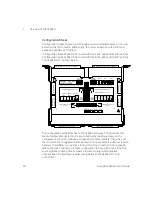
Configuration block 34934C-001 is used with the 4x32, 4x64 and 4x128 matrices.
Configuration block 34934C-002 is used with the 8x32, 8x64 and 16x32 matrices.
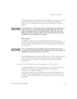
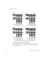
The 34934C-001 is shown below.
The configuration block attaches to the 34934A module’s D-Sub connectors.
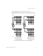
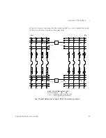
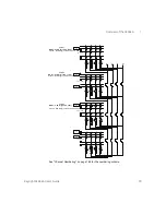
Matrix configuration (selection) is accomplished by placing jumpers on the
configuration block. You choose a configuration, place jumpers, then wire your
test circuit to the
configuration block’s
male D-Sub connectors and/or extension
headers. In addition, you will have to short two pins on each D-Sub to provide
safety interlock continuity.
All other configuration is done within the block; this
saves significant wiring time compared to direct wiring (which requires
user-supplied configuration jumper wiring between the 34934A’s D-Sub
connectors).
JUMPERS
ID
4X32
4X64
4X128
(P1), (P2)
ENABLE ROW ACCESS
J6
J5
EXTEND ROWS LEFT (J5)
EXTEND ROWS RIGHT (J4)
CONFIG
CONFIG
JUMPERS
JUMPERS
4X32
4X64
4X128
+
- 100V
J4
J3
34934C OPT001
1W/2W/MIXED
J11
J13 J12
J10
SET J10 = J11 = J12 = J13
SET J10 = J11 = J12 = J13
ALSO EXTEND TO (J6), (P2)
4X32
4X64
4X128
USE
JUMPERS
CONFIG
USE
JUMPERS
CONFIG
4X32
4X64
4X128
J7
J7
J7
J8
(P1), (P2)
DISABLE ROW ACCESS
ALSO EXTEND TO (J3), (P2)
Female D-Sub connector (to 34934A)
Female D-Sub connector (to 34934A)
Male D-Sub connector
P1
(to field wiring)
Male D-Sub connector
P2
(to field wiring)
E
xt
en
si
on
H
ea
d
er
J
5
E
xt
en
si
on
H
e
ad
e
r
J4
E
xt
en
si
on
H
ea
d
er
J
3
E
xt
en
si
on
H
ea
d
er
J
6


