3
Expanded-Row Matrix Configuration
224
Keysight 34934A User’s Guide
Creating Expanded-Row Matrices Using Configuration Blocks
Four-row matrices use the 34934C-001 configuration block. Eight-row or
sixteen-row matrices use the 34934C-002 configuration block.
Your large matrix will be built as multiples of a base configuration of 4x32, 4x64,
4x128, 8x32, 8x64 or 16x32. Thus, please thoroughly read the appropriate base
Chapter 2, “Base Matrix Configuration”
, before combining
modules and these configuration blocks to create multiples of your base matrix.
In
, you placed jumpers on each configuration block which determined
which expansion headers are available for module interconnection
.
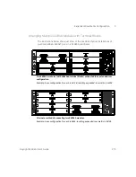
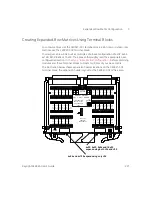
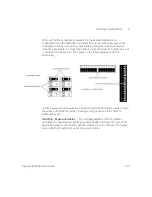
The illustration below shows expansion header locations on the 34934C-001
configuration block; the expansion header layout for the 34934C-002 is the same.
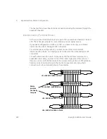
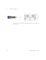
The next section shows how to make connections linking the modules through the
expansion headers.
Interconnecting Configuration Blocks
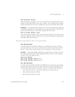
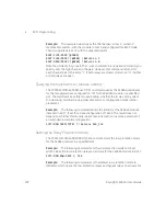
At each side of each configuration block are a pair of 20-pin extension headers.
On the right side are labeled J3 and J4; on the left side are J5 and J6. These
headers provide for row extension and row signal access, depending on the
JUMPERS
ID
4X32
4X64
4X128
(P1), (P2)
ENABLE ROW ACCESS
J6
J5
EXTEND ROWS LEFT (J5)
EXTEND ROWS RIGHT (J4)
CONFIG
CONFIG
JUMPERS
JUMPERS
4X32
4X64
4X128
+
- 100V
J4
J3
34934C OPT001
1W/2W/MIXED
J11
J13 J12
J10
SET J10 = J11 = J12 = J13
SET J10 = J11 = J12 = J13
ALSO EXTEND TO (J6), (P2)
4X32
4X64
4X128
USE
JUMPERS
CONFIG
USE
JUMPERS
CONFIG
4X32
4X64
4X128
J7
J7
J7
J8
(P1), (P2)
DISABLE ROW ACCESS
ALSO EXTEND TO (J3), (P2)
Female D-Sub connector (to 34934A)
Female D-Sub connector (to 34934A)
Male D-Sub connector
P1
(to field wiring)
Male D-Sub connector
P2
(to field wiring)
You can
expand the
matrix using
the two
left-side
headers
J5 and J6...
...or you can
expand the
matrix using
the two
right-side he
aders J2
and J4


