Overview of the 34934A
1
Keysight 34934A User’s Guide
23
Practical Examples for Selecting a Matrix Configuration Mode
The 34934A provides a wealth of configuration options, using just one module or
in combinations of up to eight modules in a single mainframe. Each module
combines four electrically separate 4x32 matrices; the 4x32 matrix is the basic
elemental component for all larger matrices which can be configured by jumper
settings and wiring.
This section provides—for each
base
matrix configuration—a description of the
matrix topology and at least one example illustrating its application.
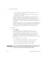
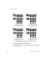
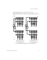
The examples include:
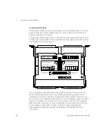
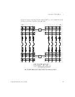
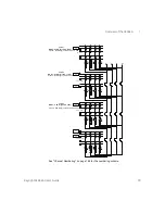
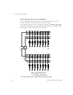
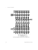
– A simplified electrical schematic of the matrix.
– Physical location of the Row Protection Resistors relative to the rows and
columns.
– Row jumpers used to create the matrix from its 4-row by 32-column elemental
components. (The row jumper represents the 2-pin CONFIG(uration) jumpers
contained on the 34934A terminal and configuration blocks. For direct wiring
applications, the rows must be physically shorted together.)
– Practical examples of physical locations to connect your test instrumentation
and DUT to the matrix.
–
Bold lines
showing each complete electrical signal path (from DUT to
instrument) through the matrix.
– The crosspoint relays included in each circuit path. Each relay has a channel
number which uniquely identifies its row-column intersection. The channel
numbering scheme is unique to each base matrix configuration (e.g. 4x32).
Row 1
Col
1
Col
3
Col
2
Col
32
100
Ω
Protection Resistor
Bypass Relay
Row
Jumper

