background image

4

Keysight 34951A User’s Guide

Additional Safety Notices

The following general safety precautions must be observed during all phases of 

operation of this instrument. Failure to comply with these precautions or with 

specific warnings or instructions elsewhere in this manual violates safety 

standards of design, manufacture, and intended use of the instrument. Keysight 

Technologies assumes no liability of the customer’s failure to comply with the 

requirements.

General

Do not use this products in any manner not specified by the manufacturer. The 

protective features of this product may be impaired if it is used in a manner not 

specified in the operation instructions. 

Before Applying Power

Verify that all safety precautions are taken. Make all connections to the unit before 

applying power.

Ground the Instrument

This product is provided with protective earth terminals. To minimize shock 

hazard, the instrument must be connected to the ac power mains through a 

grounded power cable, with the ground wire firmly connected to an electrical 

ground (safety ground) at the power outlet. Any interruption of the protective 

(grounding) conductor or disconnection of the protective earth terminal will cause 

a potential shock hazard that could result in personal injury. 

Do Not Operate in an Explosive Atmosphere

Do not operate the instrument in the presence of flammable gases or fumes.

Summary of Contents for 34951A

Page 1: ...Keysight 34951A 4 Channel Isolated D A Converter with Waveform Memory Module User s Guide ...

Page 2: ...government rights in excess of these rights customarily provided to the public to use modify reproduce release perform display or disclose commercial computer software or commercial computer software documentation No additional government requirements beyond those set forth in the EULA shall apply except to the extent that those terms rights or licenses are explicitly required from all providers o...

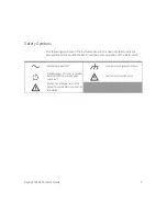
Page 3: ...ions which must be taken to maintain safe operation of the instrument Alternating current AC Frame or chassis ground terminal Standby supply Unit is not completely disconnected from ac mains when switch is off Caution risk of electric shock Caution risk of danger refer to this manual for specific Warning or Caution information ...

Page 4: ...be impaired if it is used in a manner not specified in the operation instructions Before Applying Power Verify that all safety precautions are taken Make all connections to the unit before applying power Ground the Instrument This product is provided with protective earth terminals To minimize shock hazard the instrument must be connected to the ac power mains through a grounded power cable with t...

Page 5: ...the instrument cover Do Not Modify the Instrument Do not install substitute parts or perform any unauthorized modification to the product Return the product to an Keysight Sales and Service Office for service and repair to ensure that safety features are maintained In Case of Damage Instruments that appear damaged or defective should be made inoperative and secured against unintended operation unt...

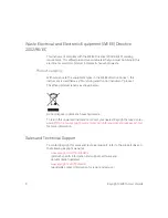
Page 6: ...nitoring and Control Instrument product The affixed product label is as shown below Do not dispose in domestic household waste To return this unwanted instrument contact your nearest Keysight Service Center or visit http about keysight com en companyinfo environment takeback shtml for more information Sales and Technical Support To contact Keysight for sales and technical support refer to the supp...

Page 7: ...nd Electronic Equipment WEEE Directive 2002 96 EC 6 Product category 6 Sales and Technical Support 6 34951A 4 Channel Isolated D A Converter with Waveform Memory Module 9 Operating Considerations 9 Level Output Mode 9 Waveform Trace Mode 10 Clock In 10 Clock Out 11 Trigger In 11 Trigger Out 11 Auto Calibration 11 34951A SCPI Programming Examples 13 Level Mode 13 Waveform Mode 13 External Clock 15 ...

Page 8: ...8 Keysight 34951A User s Guide 34951A D Sub Connector Pinout 19 34951T Terminal Block 20 ...

Page 9: ... degree 1 dry and pollution degree 2 possible condensation conditions for the DAC module Level Output Mode The module can generate voltages between 16 V DC and 16 V DC at 500 μV resolution on any or all four channels Each channel configured for voltage output has hardware remote sensing capability to ensure that an accurate voltage is present at the load With the remote sensing feature the DAC cha...

Page 10: ...ore than one channel For each channel you can designate the gain frequency and or offset for its output The waveforms are stored in volatile memory Therefore whenever power to the 34980A is cycled the volatile memory empties of data it has contained The waveform feature of the 34951A is not intended as a full featured substitute for a function generator but as a means of storing point to point upd...

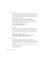
Page 11: ...etween 5 and 10 μs Auto Calibration The 34951A features auto calibration auto cal Upon receipt of the CALibration MODule command you can adjust all four channels of the DAC module The adjustments performed under complete control of the 34980A require approximately one minute per module NOTE The line between external Clock Out and external Clock In is shared You can use the external Clock Out to pr...

Page 12: ... the new calibration constants can be used while power is on But when power is lost the DAC module will revert to using the previously stored calibration constants For SCPI programming examples for the auto cal refer to page 15 WARNING Because the auto cal uses the internal DMM do not route signals on ABus1 when performing an auto cal of a DAC module Do not apply a signal to ABus1 via the Analog B...

Page 13: ...er setting the desired level send the OUTPut STATe command to close the corresponding output relay and enable outputs from the specified channels The following command outputs 2 5 V DC on DAC channels 1 and 2 for a module in slot 4 SOURce VOLTage 2 5 4001 4002 OUTPut STATe ON 4001 4002 Example Outputting a current level This command sets the output current level on the specified channels on the DA...

Page 14: ... 4002 Example Setting the amplitude of a waveform for offset and gain The following commands set the offset to 5 25 and the gain to 1 5 on DAC channels 1 and 2 of a module in slot 4 SOURce MODE VOLTage 4001 4002 SOURce FUNCtion VOLTage OFFSet 5 25 4001 4002 SOURce FUNCtion VOLTage GAIN 1 5 4001 4002 Example Setting cycle count for a waveform The following command segments turn off the trace output...

Page 15: ...rnal Trigger Example Selecting the external trigger source and issuing trigger source The following command segment enables the trigger output mode on a DAC module installed in slot 4 then enables the external trigger source on DAC channels 1 and 2 The last command issues an external trigger pulse from the module SOURce MODule TRIGger OUTPut ON 4 SOURce FUNCtion TRIGger SOURce EXTernal 4001 4002 S...

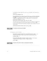
Page 16: ... time of auto cal the calibration constants are stored in volatile memory and are lost when power is turned off The RST command will not discard the calibration constants The command to secure the instrument is CALibration SECure STATe ON security code Configuring a DAC Module Example Querying the system for module identify all modules The following command returns the identify of the module insta...

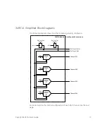
Page 17: ...igured For more detail on the internal configuration of each DAC channel see the next page 16 Bits DAC 1 16 Bits DAC 2 16 Bits DAC 3 16 Bits DAC 4 34951A Module User Supplied Connections Channel 001 Channel 002 Channel 003 Channel 004 Ext Clock In Out Ext Trig In Out Ext Clock Out Enable Ext Trig Out Enable Int Clock Int Trig ...

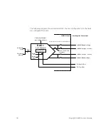
Page 18: ... ch H Sense voltage ch L Sense voltage ch H voltage current ch L voltage current Calibration Constant non volatile memory Immediate Data 25 mA Thermal Fuse resettable 34951A Module User Supplied Connections 1 of 4 Channels DAC x Control Logic Internal Clock Internal Trigger Ext Clock In Out Ext Trig In Out Sense relays are not closed in current output mode ...

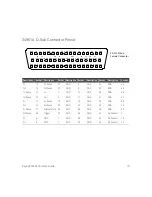
Page 19: ...ense 1L Sense 1H Sense GND 3L Sense 3H Sense GND GND 50 Pin D Sub Female Connector Description Socket Description Socket Description Socket Description Socket Description Socket 1L 15 3L Sense 21 GND 8 GND 34 GND 44 1H 16 3H Sense 22 GND 9 GND 35 GND 45 1L Sense 31 4L 3 GND 13 GND 36 GND 46 1H Sense 32 4H 4 GND 17 GND 37 GND 47 2L 11 4L Sense 19 GND 18 GND 38 GND 48 2H 12 4H Sense 20 GND 23 GND 39...

Page 20: ... Guide 34951T Terminal Block Each terminal block is labeled with the model number and the abbreviated module name In addition space is available on the label for you to write the slot number Wire Size 20 AWG Typical 18 AWG Max ...

Page 21: ... 19 D description 9 D sub pinouts 19 E external clock input 10 M module description 9 O overload fuse 10 P pinouts 19 programming examples 13 R remote sensing 9 S safety notices 4 sense terminals 9 simplified block diagrams 17 synchronization 10 T terminal block 20 trigger output source 11 triggering a DAC 11 W wiring log 20 ...

Page 22: ...22 Keysight 34951A User s Guide THIS PAGE HAS BEEN INTENTIONALLY LEFT BLANK ...

Page 23: ...ion is subject to change without notice Always refer to the Keysight website for the latest revision Keysight Technologies 2008 2019 Edition 3 July 1 2019 Printed in Malaysia 34980 90051 34980 90051 www keysight com ...

Reviews: