7
Tutorial
310
Keysight 34970A/34972A User’s Guide
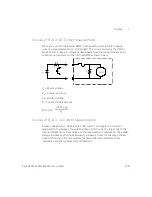
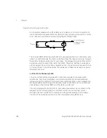
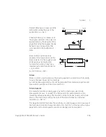
Strain gages are available in many patterns with various numbers and
configurations of elements. The most common element is the single gage form
shown below. Multi-element strain gages, also called
rosettes
, are used to
measure components of strain in different directions. Two-element (90°) and
three-element (45° or 60°) configurations are the
most common.
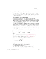
Common Uses for Strain Gages
Strain gages are used to sense many types of physical parameters. Strain gages
are primarily a force-sensing device. Force is measured indirectly by measuring
the deformation of a test body to a known applied force thus producing a
resistance change proportional to the applied force. Many other physical
quantities can be measured through force measurements. Common applications
of strain gages include weight, pressure, flow, and level measurements.
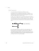
Making Strain Gage Measurements
A
Wheatstone bridge
is commonly used to enable instruments with low-sensitivity
measuring capabilities to measure small resistance changes common in strain
measurements. Instruments with high-resolution resistance measuring
capabilities, like the 34970A/34972A internal DMM, can directly measure small
resistance changes with high precision and linearity. You should also use the
4-wire resistance method when measuring strain gages to eliminate system
cabling errors.
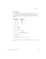
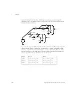
An initial, unstrained, gage resistance measurement is used as the reference (R
0
)
measurement from which strain (
Δ
R / R
0
) is measured. For best results, you
should perform this reference measurement after the strain gage has been
mounted to the test body. The table below shows the resistance changes
corresponding to 1
με
strain for common gage factor and unstrained gage
resistance values.
HI Source
HI Sense
LO Sense
LO Source


