Closed-Loop Scanners
5
Keysight 5500 SPM User’s Guide
5-5
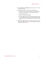
Figure 9-3
Advanced tab settings for CL calibration
9
Without a sample in place, use the laser alignment controls and
camera window to align the laser and detector for Contact AFM
mode.
10
In the Scan and Motor
window enter:
a
A very large number (e.g., 9999) for the Scan
Size. It will adjust
automatically to the maximum allowed value
.
b
Speed of
1-2 lines/second
.
c
Resolution of
256
.
11
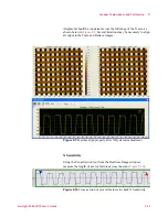
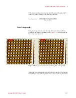
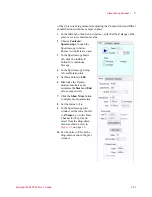
In the Realtime Images window, create two image buffers with the
following settings:
•
Input set to
X Sensor
.
•
Flattening set to
None
.
•
Display Range
set to
-10 V to +10 V
.
•
For one image display
Trace
and for the other display
Retrace
.
•
Set both buffers to
Main
scan mode.
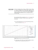
12
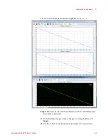
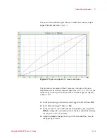
Choose
Tools > Realtime Cross Section
so the individual scan lines
will be displayed in the Cross Section window. Set the range to
±10 V.


