Keysight 5500 SPM Components
5
Keysight 5500 SPM User’s Guide
5-9
Detector
The photodiode detector, composed of four separate quadrants, receives
the reflection of the laser spot off the back of the cantilever. The top and
bottom halves of the detector monitor the cantilever deflection (the
Deflection signal) for AFM imaging, while the two side halves measure
the twist of the cantilever (the Friction signal) for lateral force imaging.
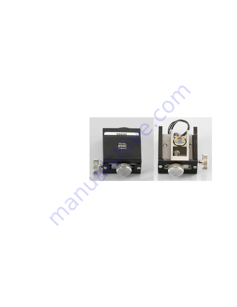
The detector is held in the scanner by magnets on the detector housing
and in the scanner. Two thumbwheels enable alignment of the detector
in both directions. There are also four DIP switches to enable or disable
the gain of the signal from the detector. Enabling the gain is useful when
using very non-reflective cantilevers to ensure a high enough Sum value
is provided to the control system.
Figure 2-6
Detector assembly, top and bottom views


